4.Drill6 mountingholesin
holesandinsert3/8-insteelshields(anchors)..
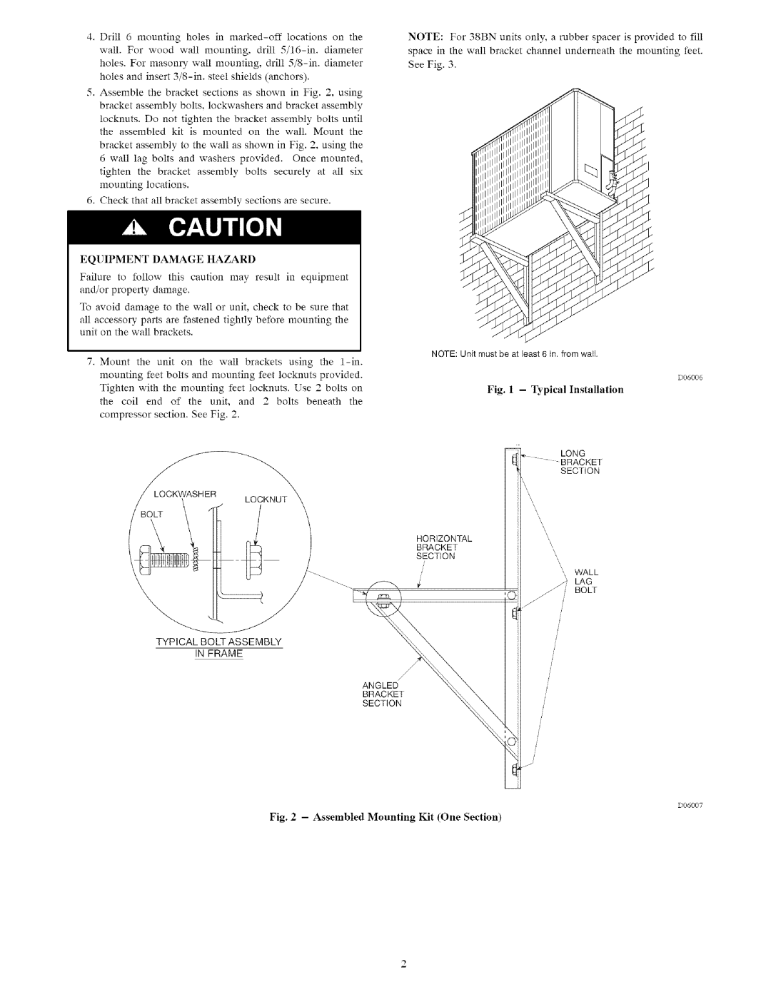
5.Assemblethebracketsectionsasshownin Fig.2,using bracketassemblybolts,lockwashersandbracketassembly locknutsDonottightenthebracketassemblyboltsuntil. theassembledkit is mountedonthewall.Mountthe
bracketassemblytothewallasshowninFig.2,usingthe
6walllagboltsandwashersprovidedOncemounted,. tightenthebracketassemblyboltssecurelyat all six mountinglocations.
6.Checkthatallbracketassemblysectionsaresecure.
EQUIPMENTDAMAGEHAZARD
Failureto followthiscautionmayresultin equipment and/orpropertydamage.
Toavoiddamagetothewallorunitchecktobesurethat. allaccessorypartsarefastenedtightlybeforemountingthe unitonthewallbrackets.
/
LOCKWASHERLOCKNUT
/BOLT\ /
NOTE:For38BNunitsonly,arubberspacerisprovidedtofill
spaceinthewallbracketchannelunderneaththemountingfeet. SeeFig3. .
NOTE: Unit must be at least, ; in. from wail.
D06006
Fig. 1 - Typical Installation
;KET
SECTION
HORIZONTAL
BRACKET
SECTION
', WALL
/
/_.} LAG
j / BOLT
TYPICAL BOLT ASSEMBLY
IN FRAME
ANGLED
BRACKET
SECTION
D06007
