ASSEMBLY
Assembly requires two people. Place all parts of the stepper in a cleared area and remove the packing materials. Do not dispose of the packing materials until assembly is completed. Read each step carefully before beginning.
THE FOLLOWING TOOLS ARE REQUIRED FOR ASSEMBLY: The included allen wrench | , a phillips | ||
screwdriver | , and a rubber mallet | . |
|
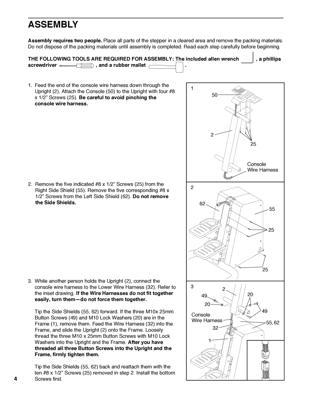
1.Feed the end of the console wire harness down through the Upright (2). Attach the Console (50) to the Upright with four #8 x 1/2Ó Screws (25). Be careful to avoid pinching the console wire harness.
2.Remove the five indicated #8 x 1/2Ó Screws (25) from the Right Side Shield (55). Remove the five corresponding #8 x 1/2Ó Screws from the Left Side Shield (62). Do not remove the Side Shields.
3.While another person holds the Upright (2), connect the console wire harness to the Lower Wire Harness (32). Refer to the inset drawing. If the Wire Harnesses do not fit together easily, turn themÑdo not force them together.
Tip the Side Shields (55, 62) forward. If the three M10x 25mm Button Screws (49) and M10 Lock Washers (20) are in the Frame (1), remove them. Feed the Wire Harness (32) into the Frame, and slide the Upright (2) onto the Frame. Loosely thread the three M10 x 25mm Button Screws with M10 Lock Washers into the Upright and the Frame. After you have threaded all three Button Screws into the Upright and the Frame, firmly tighten them.
Tip the Side Shields (55, 62) back and reattach them with the
ten #8 x 1/2Ó Screws (25) removed in step 2. Install the bottom
4Screws first.
1 |
| |
50 |
| |
2 |
| |
| 25 | |
| Console | |
| Wire Harness | |
2 |
| |
62 | 55 | |
| ||
| 25 | |
| 25 | |
3 | 2 | |
| ||
49 | 20 | |
20 |
| |
Console | 49 | |
| ||
Wire Harness | 55,62 | |
32 | ||
| ||
1 |
|