3.Move gear shift lever {Fig. 2) to "NEUTRAL" position.
4.Place parking brake (Fig. 2) in "ENGAGED" posi- tion. Raise parking brake lever and hold in "EN-
GAGED" position, Release
5, Disengage mower blade clutch lever (Fig. 2 - Inset).
i,
FROM THE SPARK PLUGIS) AND KEEP WIRE(S) AWAY FROM THE PLUG(S) TO PREVENT INJURY FROM ACCIDENTAL
MOWER
LOWER
BLADE
MANDREL
STARTING.
ii
6.Remove mower from tractor. Refer to "To Remove Mower" in your tractor owners manual. Turn the mower upside down.
7.Using a 9/16" wrench remove the bolts, Iockwashers and washers securing the mower blades to the mandrel assemblies. Save hardware
for later use when mower is used without grass catcher.
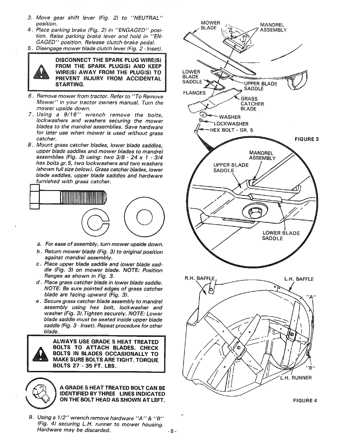
8.Mount grass catcher blades, lower blade saddles, upper blade saddles and mower blades to mandrel assemblies (Fig, 3) using: two 3/8 - 24 x 1 - 3/4 hex bolts gr. 5, two Iockwashers and two washers (shown full size below). Grass catcher blades, lower blade saddles, upper blade saddles and hardware furnished with grass catcher.
•UPPER BLADE SADDLE
FLANGES
GRASS
CATCHER
BLADE
WASHER
_LOCKWASH ER
HEX BOLT - GR. 5
FIGURE 3
HJlltlltnlnMIHrlIHtnlfD
L_I
a.For ease of assembly, turn mower upside down.
b.Return mower blade (Fig. 3) to original position against mandrel assembly.
c.Place upper blade saddle and lower blade sad- dle (Fig. 3) on mower blade. NOTE: Position
flanges as shown in Fig. 3. | a.H. | L.H. BAFFLE | |
d. Place grass catcher blade in lower blade saddle. |
| ||
NOTE: Be sure pointed edges of grass catcher |
| ||
blade are facing upward (Fig. 3). |
|
| |
e . Secure grass catcher blade assembly to mandrel |
| ||
assembly using hex bolt, Iockwasher and |
| ||
washer (Fig. 3). Tighten securely. NOTE: Lower |
| ||
blade saddle must be seated inside upper blade |
| ||
saddle (Fig. 3 |
| ||
blade. |
|
|
|
1'lit ' | _ | ii |
|
ALWAYS USE GRADE 5 HEAT TREATED |
| ||
BOLTS IN BLADES OCCASIONALLY TO |
| ||
BOLTS TO ATTACH BLADES. CHECK |
| ||
MAKE SURE BOLTS ARE TIGHT, TORQUE |
| ||
BOLTS 27 - 35 FT. LBS. |
|
| |
i | i, | i |
|
A GRADE 5 HEAT TREATED BOLT CAN BE |
| ||
IDENTIFIED BY THREE LINES INDICATED |
| ||
ON THE BOLT HEAD AS SHOWN AT LEFT. | FIGURE 4 | ||
9.Using a 1/2" wrench remove hardware "'A'" & "'B'"
(Fig. 4) securing L.H. runner to mower housing. |
|
Hardware may be discarded. | .5. |