FIGURE 5
FIGURE 6
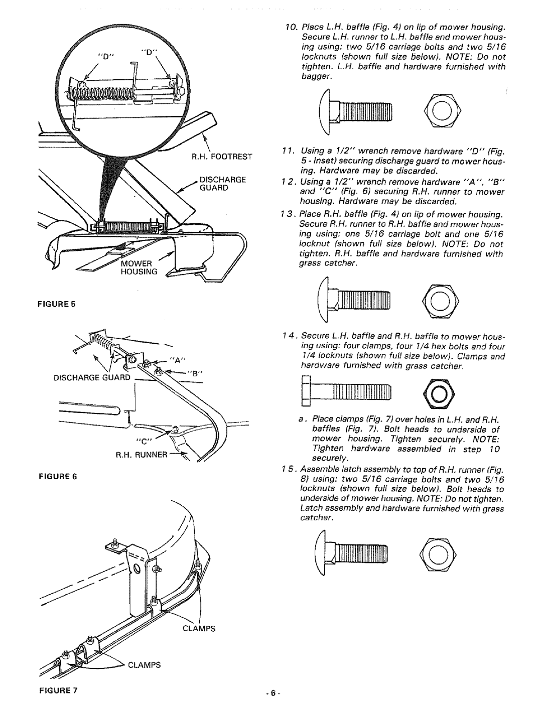
R.H. FOOTREST
DISCHARGE
GUARD
MOWER
HOUSING
CLAMPS
10.Place L.H, baffle (Fig. 4) on lip of mower housing. Secure L.H. runner to L.H. baffle and mower hous-
ing using: two 5/16 carriage bolts and two 5/16
locknuts (shown full size below). NOTE: Do not
tighten. L.H, baffle and hardware furnished with bagger.
1 1. Using a 1/2" wrench remove hardware "'D" (Fig. 5 - Inset) securing discharge guard to mower hous- ing. Hardware may be discarded,
1 2, Using a 1/2"' wrench remove hardware "'A", "'B" and "'C" (Fig, 6) securing R.H. runner to mower housing. Hardware may be discarded.
1 3. Place R.H. baffle (Fig. 4) on lip of mower housing. Secure R.H, runner to R,H. baffle and mower hous-
ing using: one 5/16 carriage bolt and one 5/16
locknut (shown full size below). NOTE: Do not
tighten. R.H, baffle and hardware furnished with grass catcher.
14.Secure L,H. baffle and R.H. baffle to mower hous- ing using: four clamps, four 1/4 hex bolts and four 1/4 Iocknuts (shown futl size below). Clamps and hardware furnished with grass catcher,
Itlll!!lllltllllJi
a.Place clamps (Fig. 7) overholes in L.H. and R, H.
baffles (Fig, 7). Bolt heads to underside of
mower housing, Tighten securely. NOTE:
Tighten hardware assembled in step 10 securely.
15. Assemble latch assembly to top of R.H. runner (Fig.
8)using: two 5/16 carriage bolts and two 5/16
Iocknuts (shown full size below). Bolt heads to underside of mower housing, NOTE: Do not tighten.
Latch assembly and hardware furnished with grass catcher,
©
FIGURE 7 | - 6 - |