=,,_. I===,, | =,H= | ,,, |
SERVmCEAN
Raise mower to its highest position
oAt the midpoint of both sides of mower, measure height
from bottom edge of mowerto ground Distance"A" on both sides of mower should be the same or within 1/4" of each other
oIf adjustment is necessary, make adjustment on one side of mower onty.1
=To raise one side of mower, tighten lift link adjustment nut on that side
=To lower one side of mower, loosen lift link adjustment nut on that side
NOTE: Each fu'llturn of adjustment nut wilt change mower
he!ght about 1/8"r
" Recheck measurements after adjusting
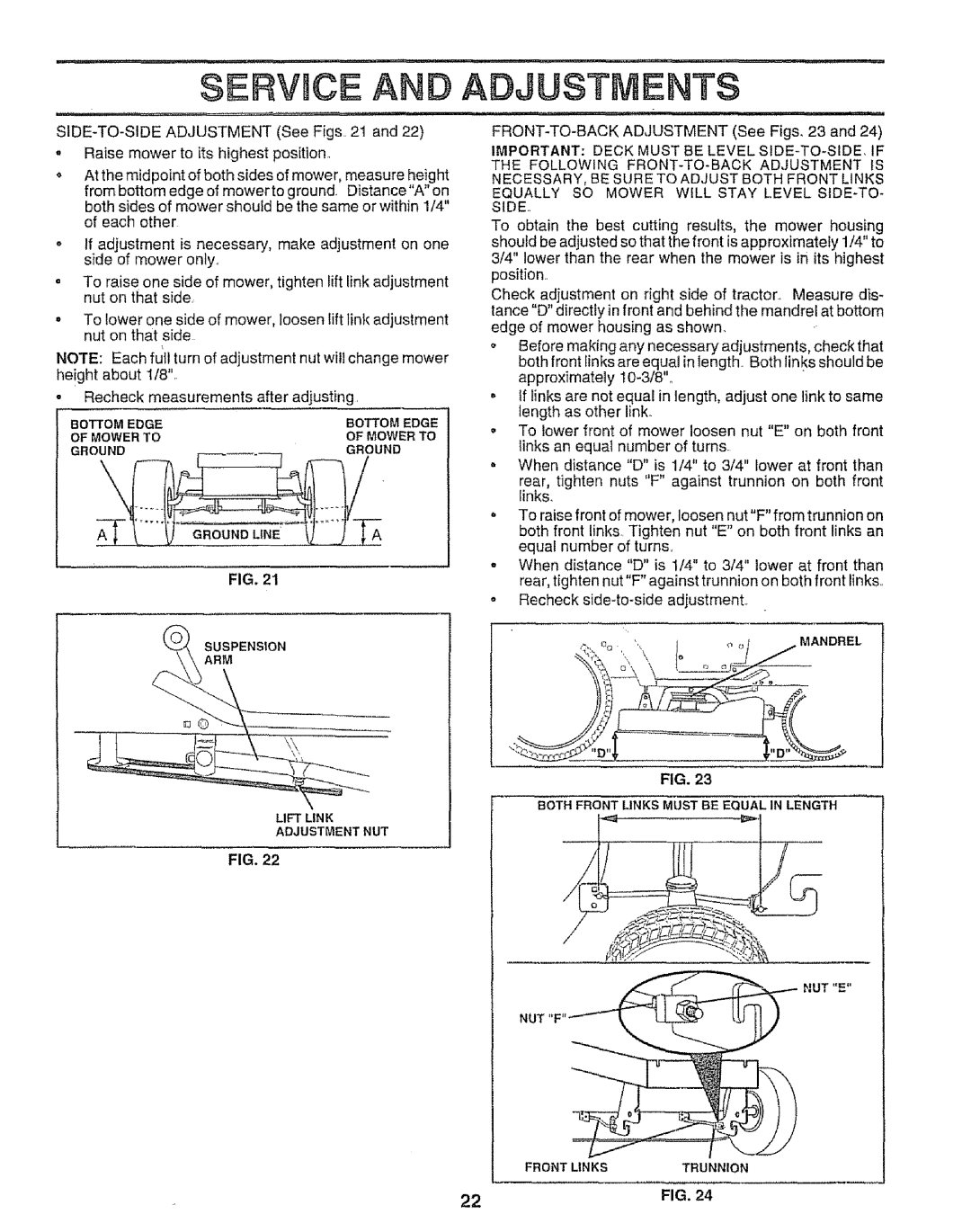
BOTTOM EDGE | BOTTOM EDGE |
OF MOWER TO | OF MOWER TO |
GROUND | GROUND |
GROUND LINE
FIG. 21
SUSPENSION
ARM
LIFT LINK
ADJUSTMENT NUT
n, ,=,,=,,,,,=,,,= | n =,== |
ADJUSTMENTS
, | ,,Hu,iul | ,u | " | = n, 1, ,11 |
IMPORTANT: DECK MUST BE LEVEL
To obtain the best cutting results, the mower housing should be adjusted so that the front is approximately 1/4" to 3/4" lower than the rear when the mower is in its highest position
Check adjustment on right side of tractor_ Measure dis- tance "D" directly in front and behind the mandrel at bottom edge of mower housing as shown.
oBefore making any necessary adjustments, check that both front links are equal in length, Both links should be approximately
oIf links are not equal in length, adjust one link to same length as other link.
oTo lower front of mower loosen nut "E" on both front links an equal number of turns.
oWhen distance "D" is 1/4" to 3/4" Iower at front than
rear, tighten nuts "F" against trunnion on both front iinks.
. To raise front of mower, loosen nut"F" from trunnion on both front links Tighten nut "E" on both front links an equal number of turns,,
. When distance "D" is 1/4" to 3/4" lower at front than rear, tighten nut"F" against trunnion on both front links.,
o Recheck
m % ', | _ _,z | MANDREL |
to
FIG, 23
BOTH FRONT LINKS MUST BE EQUAL IN LENGTH
FIG. 22
NUT "E"
NUT "F"
FRONT LINKS | TRUNNION |
22 | FIG. 24 |