Digital Access Keypad Manual
PREPARING TO PROGRAM THE KEYPAD
Before programing the
1.The master code
2.The user code or codes
3.The inhibit/lockout code
4.Configuration of the relay output
5.Result of improper code entry
GETTING STARTED
A master code is required to program the keypad. The default master code is set to "0000." To change the master code, go to page 7 and follow the instructions for "MASTER CODE BYPASS (DAP jumper)."
Once the master code is set, review the programming options and decide exactly what the keypad will do, including the format of the user access codes as well as how the keypad responds via the relay output, buzzer and LEDs. Note that in every case the basic steps for programming are:
1. | Enter the master code, followed by the * key, which puts you in programming mode. |
2. | Enter the programming codes defined in the various sections as needed, followed by the # key. |
3. | Enter the * key again to exit the programming mode. |
Note: A rapid string of 5 beeps and/or 5 LED flashes indicates an error, while 2 beeps indicates that the entry has been accepted.
PROGRAMMING NOTES
1.Master code: The
2.Factory defaults:
Master code | 0000 |
_________________________________________________________________________ | |
User code length | 4 to 8 digits |
_________________________________________________________________________ | |
Main relay output time | 1 second |
_________________________________________________________________________ | |
Wrong code lockout | 10 tries / 30 second |
_________________________________________________________________________ | |
Output activation announcer | ON |
_________________________________________________________________________ | |
User code entry mode | Manual |
_________________________________________________________________________ | |
Digital Access Keypad Manual
USER PROGRAMMING
Enter Programming Mode |
|
| |||
Enter Master code | Confirm |
| Function | ||
X | X X X |
| * |
| Enter into programming mode |
|
|
|
| ||
Note: X X X X indicates the Master code. |
| ||||
Note: For |
| ||||
|
|
| |||
Adding Or Changing Master And User Codes |
| ||||
Option | User ID | Access code | Confirm | Function | |
0 |
|
| 4 to 8 digits | # | Master Code |
1 |
| 00 to 99 | 4 to 8 digits | # | Add or change up to 100 User Codes |
Note: No user code can be the same code as the master code or the inhibit/lockout code.
Delete A User
To delete a user who has left the company or who no longer has authority to enter the protected area:
1. Enter Programming Mode:
Enter Master code | Confirm | Function |
| EXIT THE | |
X X X X |
| * | Enter into programming mode |
| PROGRAMMING |
|
| ||||
| EXIT | ||||
2. Delete code |
|
| MODE BY PRESSING | ||
|
|
|
| ||
| Confirm | Function |
| THE * KEY | |
Option | User ID |
| |||
1 | 00 to 99 | # | Deletes specific user ID |
|
|
|
|
|
|
|
|
Set Inhibit / Lockout Code (see page 2) |
|
| |||
1. Enter Programming Mode: |
|
|
| ||
Enter Master code | Confirm | Function | Note: to set | ||
X X X X |
|
| * | Enter into programming mode | |
|
| lockout duration, | |||
2. Set code |
|
| |||
|
|
|
| see page 6 | |
Option | Access code | Confirm | Function |
| |
2 1 | 4 to 8 digits |
| # | Sets inhibit/lockout code |
|
|
|
|
|
|
|
BUZZER AND LED SIGNALS
The keypad's
| Status | Buzzer Tones* | Amber LED Flashes |
_____________________________________________________________________________________ | |||
1. | In programming mode | N/A | ON |
_____________________________________________________________________________________ | |||
2. | Successful key entry | 1 beep | 1 flash |
_____________________________________________________________________________________ | |||
3. | Successful code entry | 2 beeps | 2 flashes |
_____________________________________________________________________________________ | |||
4. | Unsuccessful code entry | 5 beeps | 5 flashes |
_____________________________________________________________________________________ | |||
5. | DAP jumper not replaced | Continuous beeps | Continuous flashes |
_____________________________________________________________________________________ | |||
6. | In standby mode | N/A | 1 flash in |
_____________________________________________________________________________________ | |||
7. | Output relay activated | N/A | |
NOTE: * The buzzer can be disabled through programming option 83.
** The output relay activated beep can be disabled through programming option 82.
Keypress beep | ON |
_______________________________________________________________________ | |
Silent operation | OFF |
3.Code operation: User codes are each four to eight digits and are assigned to
The administrator can easily delete the code of one user via the
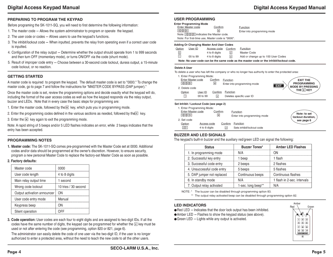
LED INDICATORS
Red LED
Amber
RedGreen
1 ![]()
![]() 2
2 ![]()
![]() 3
3
4 ![]()
![]() 5
5 ![]()
![]() 6
6
7 ![]()
![]() 8
8 ![]()
![]() 9
9
*![]()
![]() 0
0 ![]()
![]() #
#
ENFORCER
Page 4 |
| Page 5 |
|