Installation Manual
ENFORCER®
ST-HB105-TTQ
Voltage Booster
Introduction:
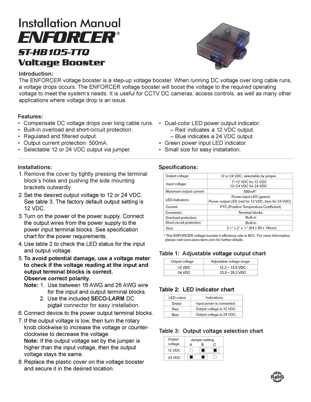
The ENFORCER voltage booster is a
Features:
•Compensate DC voltage drops over long cable runs.
•
•Regulated and filtered output.
•Output current protection: 500mA.
•Selectable 12 or 24 VDC output via jumper.
•
–Red indicates a 12 VDC output.
–Blue indicates a 24 VDC output.
•Green power input LED indicator.
•Small size for easy installation.
Installations:
1.Remove the cover by tightly pressing the terminal block’s holes and pushing the side mounting brackets outwardly.
2.Set the desired output voltage to 12 or 24 VDC. See table 3. The factory default output setting is 12 VDC.
3.Turn on the power of the power supply. Connect the output wires from the power supply to the power input terminal blocks. See specification chart for the power requirements.
4.Use table 2 to check the LED status for the input and output voltage.
5.To avoid potential damage, use a voltage meter to check if the voltage reading at the input and output terminal blocks is correct.
Observe correct polarity.
Note: 1. Use between 16 AWG and 26 AWG wire for the input and output terminal blocks.
2.Use the included
6.Connect device to the power output terminal blocks.
7.If the output voltage is low, then turn the rotary knob clockwise to increase the voltage or counter- clockwise to decrease the voltage.
Note: If the output voltage set by the jumper is higher than the input voltage, then the output voltage stays the same.
8.Replace the plastic cover on the voltage booster and secure it in the desired location.
Specifications:
Output voltage: | 12 or 24 VDC, selectable by jumper | |
Input voltage: | 7~12 VDC for 12 VDC | |
12~24 VDC for 24 VDC | ||
| ||
Maximum output current: | 500mA* | |
LED indicators: | Power input LED (green) | |
Power output LED (red for 12 VDC, blue for 24 VDC) | ||
| ||
Current | PTC (Positive Temperature Coefficient) | |
|
| |
Connector: | Terminal blocks | |
Overload protection: | ||
Short circuit protection: | ||
Size: | 21/2” x 2” x 3/4” (64 x 50 x 19mm) |
*This ENFORCER voltage booster’s efficiency rate is 85%. For more information, please visit
Table 1: Adjustable voltage output chart
Output voltage | Adjustable voltage range |
12 VDC | 12.2 ~ 13.5 VDC |
24 VDC | 23.0 ~ 25.2 VDC |
|
|
Table 2: LED indicator chart
LED colors | Indications |
Green | Input power is connected. |
Red | Output voltage is 12 VDC. |
Blue | Output voltage is 24 VDC. |
Table 3: Output voltage selection chart
Output |
|
| Jumper setting | ||||||||
voltage |
| A |
| B |
| C | |||||
12 VDC |
|
|
|
|
|
|
|
|
|
|
|
|
|
|
|
|
|
|
|
|
|
| |
|
|
|
|
|
|
|
|
|
|
|
|
|
|
|
|
|
|
|
|
|
|
|
|
24 VDC |
|
|
|
|
|
|
|
|
|
|
|
|
|
|
|
|
|
|
|
|
|
| |
|
|
|
|
|
|
|
|
|
|
| |
|
|
|
|
|
|
|
|
|
|
|
|
