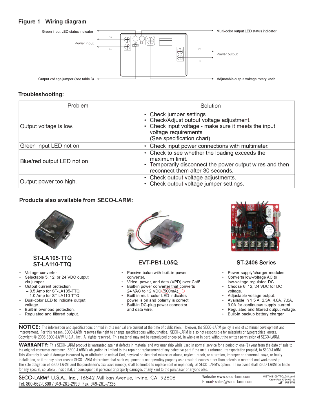
Figure 1 - Wiring diagram
Green input LED status indicator
Power input
Output voltage jumper (see table 3)
(+) |
|
24 | 12 |
|
(+)
Power output
Adjustable output voltage rotary knob
Troubleshooting:
Problem |
| Solution | |
|
|
| |
| • | Check jumper settings. | |
| • | Check/Adjust output voltage adjustment. | |
Output voltage is low. | • | Check input voltage - make sure it meets the input | |
|
| voltage requirements. | |
|
| (See specification chart). | |
Green input LED not on. | • | Check input power connections with multimeter. | |
| • Check to see whether the loading exceeds the | ||
Blue/red output LED not on. |
| maximum limit. | |
• Temporarily disconnect the power output wires and then | |||
| |||
|
| reconnect them after 30 seconds. | |
Output power too high. | • | Check output voltage adjustments. | |
• | Check output voltage jumper settings. | ||
| |||
Products also available from SECO-LARM:
|
|
|
| |
|
|
| ||
• | Voltage converter. | • Passive balun with | • | Power supply/charger modules. |
• Selectable 5, 12, or 24 VDC output | converter. | • | Converts | |
| via jumper. | • Video, power, and data (VPD) over Cat5. |
| |
• | Output current protection: | • | • Choose 6, 12, 24 VDC for DC | |
| – 0.5 Amp for | 24 VAC to 12 VDC (500mA). |
| voltage. |
| – 1.0 Amp for | • | • | Adjustable voltage output. |
• | power is on and polarity is correct. | • Available in 1.5 A, 2.5A, 4.0A, 7.0A, | ||
| voltage. | • |
| 9.0A for continuous supply current. |
• | and data wire. | • Regulated and filtered output voltage. | ||
• Regulated and filtered output. |
| • | ||
NOTICE: The information and specifications printed in this manual are current at the time of publication. However, the
WARRANTY: This
This Warranty is void if damage is caused by or attributed to acts of God, physical or electrical misuse or abuse, neglect, repair, or alteration, improper or abnormal usage, or faulty installation, or if for any other reason
The sole obligation of
Website: | |
Tel: | |
|
Order Part
PITSW1
