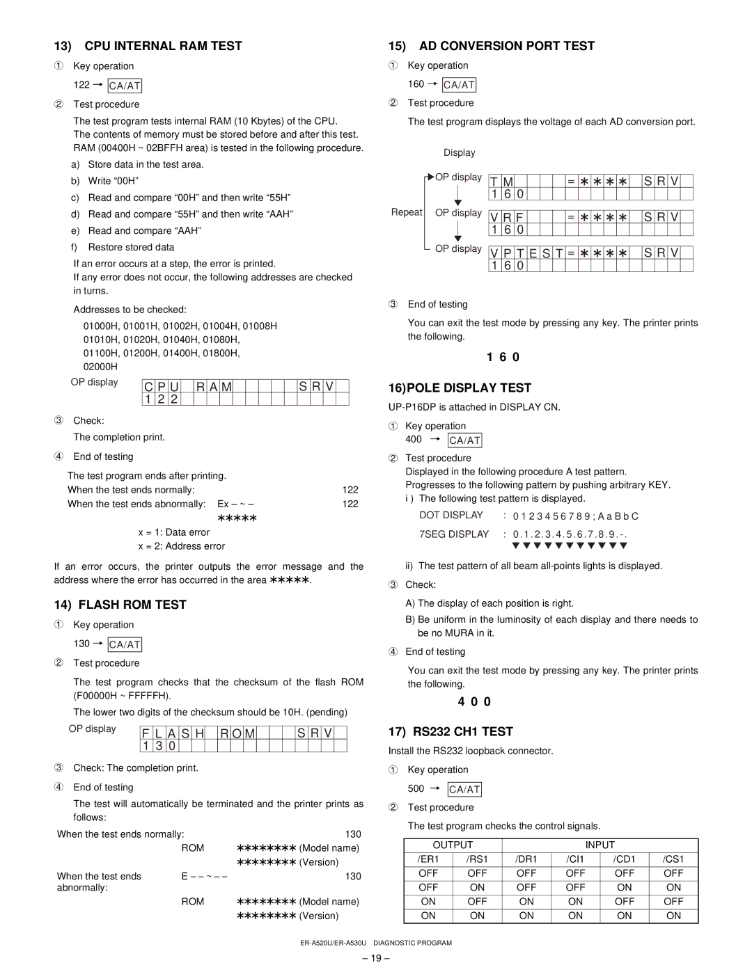
13)CPU INTERNAL RAM TEST

1Key operation

122 3 CA/AT

2 Test procedure

The test program tests internal RAM (10 Kbytes) of the CPU.

The contents of memory must be stored before and after this test.

RAM (00400H ~ 02BFFH area) is tested in the following procedure.

15)AD CONVERSION PORT TEST

1Key operation

160 3 CA/AT

2Test procedure

The test program displays the voltage of each AD conversion port.

a)

Store data in the test area.

b)

Write “00H”

c)

Read and compare “00H” and then write “55H”

d)

Read and compare “55H” and then write “AAH”

e)

Read and compare “AAH”

f)

Restore stored data

If an error occurs at a step, the error is printed.

If any error does not occur, the following addresses are checked in turns.

Display

OP display

Repeat OP display

OP display

T

M


=


S

R

V


1

6

0


V

R

F


=


S

R

V


1

6

0


V

P

T

E

S

T

=


S

R

V


1

6

0


Addresses to be checked:

01000H, 01001H, 01002H, 01004H, 01008H 01010H, 01020H, 01040H, 01080H, 01100H, 01200H, 01400H, 01800H, 02000H

3End of testing

You can exit the test mode by pressing any key. The printer prints the following.

1 6 0

OP display


C

P

U


R

A

M


S

R

V


16)POLE DISPLAY TEST


1

2

2


UP-P16DP is attached in DISPLAY CN.

3 Check:


1 Key operation


The completion print.


400 3

CA/AT


4 End of testing


2 Test procedure


The test program ends after printing.


Displayed in the following procedure A test pattern.


Progresses to the following pattern by pushing arbitrary KEY.

When the test ends normally:

122

i )

The following test pattern is displayed.

When the test ends abnormally: Ex – ~ –

122


*****


DOT DISPLAY

: 0 1 2 3 4 5 6 7 8 9 ; A a B b C


x = 1: Data error


7SEG DISPLAY

: 0 . 1 . 2 . 3 . 4 . 5 . 6 . 7 . 8 . 9 . - .


x = 2: Address error


c c c c c c c c c c c

If an error occurs, the printer outputs the error

message and the

ii)

The test pattern of all beam all-points lights is displayed.

address where the error has occurred in the area *****.

3 Check:


14) FLASH ROM TEST


A) The display of each position is right.

1 Key operation


B) Be uniform in the luminosity of each display and there needs to


be no MURA in it.


130 3

CA/AT


4 End of testing


2 Test procedure


You can exit the test mode by pressing any key. The printer prints


The test program checks that the checksum of the flash ROM

the following.


(F00000H ~ FFFFFH).


4 0 0


The lower two digits of the checksum should be 10H. (pending)

OP display

F

L

A

S

H


R

O

M


S

R

V


1

3

0


3Check: The completion print.

4End of testing

The test will automatically be terminated and the printer prints as follows:

When the test ends normally:

130


ROM

******** (Model name)


******** (Version)

When the test ends

E – – ~ – –

130

abnormally:


ROM

******** (Model name)


******** (Version)

17) RS232 CH1 TEST

Install the RS232 loopback connector.

1Key operation

500 3 CA/AT

2Test procedure

The test program checks the control signals.

OUTPUT


INPUT


/ER1

/RS1

/DR1

/CI1


/CD1

/CS1


OFF

OFF

OFF

OFF


OFF

OFF


OFF

ON

OFF

OFF


ON

ON


ON

OFF

ON

ON


OFF

OFF


ON

ON

ON

ON


ON

ON


ER-A520U/ER-A530U DIAGNOSTIC PROGRAM

– 19 –

Page 20
Image 20
Sharp ER-A530, ER-A520 service manual CPU Internal RAM Test, AD Conversion Port Test, 16POLE Display Test, Flash ROM Test

ER-A520, ER-A530 specifications

The Sharp ER-A530 and ER-A520 are advanced electronic cash registers designed to cater to the needs of small and medium-sized businesses. These models are known for their reliability, user-friendly interfaces, and robust features that enhance operational efficiency in retail environments.

One of the most prominent features of the ER-A530 and ER-A520 is their advanced transaction processing capabilities. Equipped with a high-speed thermal printer, these registers ensure quick and efficient printing of receipts, which is essential for maintaining customer satisfaction during busy hours. The print quality is clear and legible, providing customers with a professional receipt that reflects the brand's identity.

Both models boast an intuitive and ergonomic keypad layout, making it easy for staff to learn and operate the register with minimal training. The bright and easy-to-read LCD display is another key characteristic, allowing operators to view transaction details clearly in various lighting conditions. This user-friendly design reduces errors and speeds up the checkout process, making it ideal for busy retail settings.

In terms of storage capacity, the Sharp ER-A530 and ER-A520 can handle a substantial number of PLUs (Price Look Up codes), accommodating a wide range of products and services. This extensive capability is particularly beneficial for businesses with a diverse inventory, as it enables quick access to pricing and product information without needing to enter details manually for every sale.

Connectivity is another strong point for these registers. The ER-A530 and ER-A520 support various peripheral devices, including barcode scanners, cash drawers, and kitchen printers. This versatility allows businesses to create a more streamlined checkout process, enhancing overall operational efficiency.

Additionally, both models include advanced reporting features that allow business owners to track sales trends, monitor inventory levels, and analyze performance over time. This analytical capability is crucial for making informed decisions about inventory management, staffing, and sales strategies.

Moreover, the security features in the ER-A530 and ER-A520 ensure that sensitive financial data is protected. With password-protected access to programming and certain functions, businesses can safeguard against unauthorized use while maintaining a secure environment for transactions.

In summary, the Sharp ER-A530 and ER-A520 electronic cash registers stand out in the market for their reliable performance, user-friendly design, and a comprehensive set of features that accommodate the unique needs of retailers. These registers not only enhance customer service but also provide critical insights for inventory and sales management, making them an excellent choice for businesses looking to streamline their operations.