Flow Chart of Troubleshooting
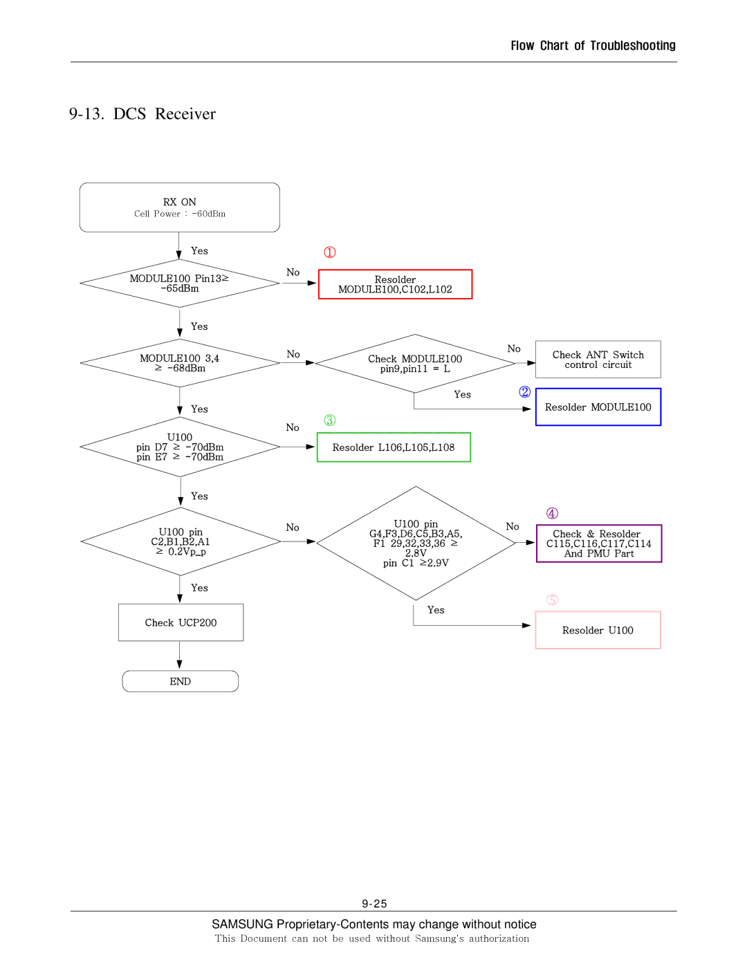
9-13. DCS Receiver
RX ON
Cell Power :
Yes
MODULE100 Pin13≥
Yes
MODULE100 3,4
≥
Yes
U100
pin D7 ≥
Yes
U100 pin
C2,B1,B2,A1
≥ 0.2Vp_p
Yes
No
No
No
No
①
Resolder
MODULE100,C102,L102
No
Check MODULE100
pin9,pin11 = L
Yes ②
③
Resolder L106,L105,L108
U100 pin | No | ||
G4,F3,D6,C5,B3,A5, | |||
|
| ||
F1 29,32,33,36 ≥ |
|
| |
|
| ||
2.8V |
|
| |
pin C1 ≥2.9V |
|
| |
Check ANT Switch
control circuit
Resolder MODULE100
④
Check & Resolder
C115,C116,C117,C114
And PMU Part
Check UCP200
END
⑤
Yes
Resolder U100
SAMSUNG Proprietary-Contents may change without notice
This Document can not be used without Samsung's authorization
