30" Microwave Drawer Measurements
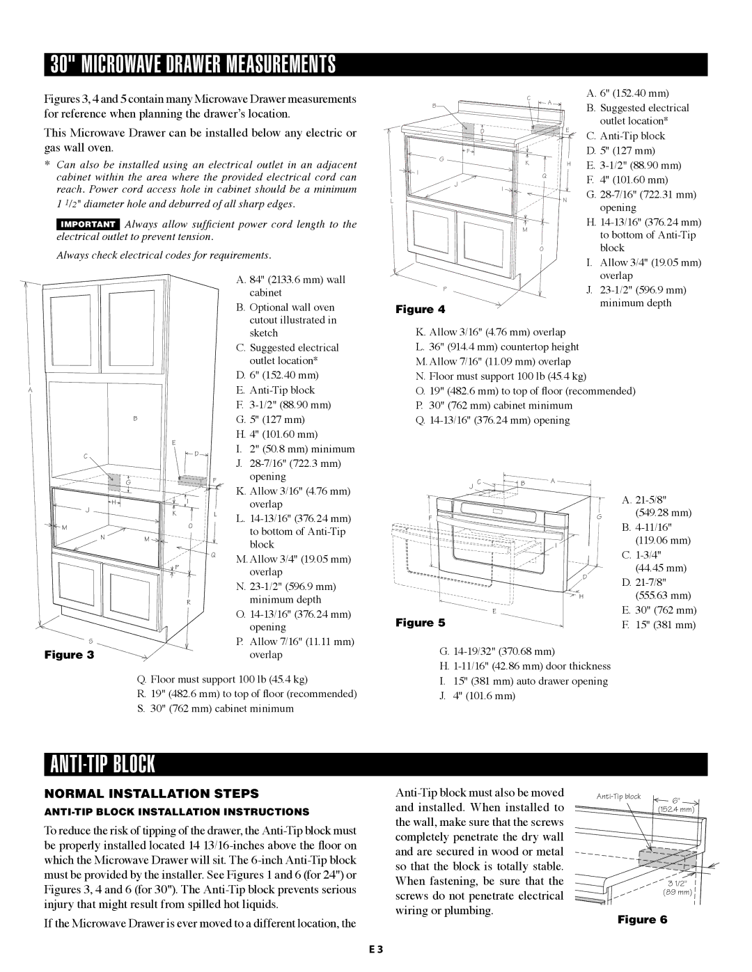
Figures 3, 4 and 5 contain many Microwave Drawer measurements for reference when planning the drawer’s location.
This Microwave Drawer can be installed below any electric or gas wall oven.
*Can also be installed using an electrical outlet in an adjacent cabinet within the area where the provided electrical cord can reach. Power cord access hole in cabinet should be a minimum 1 1/2" diameter hole and deburred of all sharp edges.
IMPORTANT Always allow sufficient power cord length to the electrical outlet to prevent tension.
Always check electrical codes for requirements.
|
| A. 84" (2133.6 mm) wall |
|
| cabinet |
|
| B. Optional wall oven |
|
| cutout illustrated in |
|
| sketch |
|
| C. Suggested electrical |
|
| outlet location* |
|
| D. 6" (152.40 mm) |
A |
| E. |
|
| F. |
| B | G. 5" (127 mm) |
| E | H. 4" (101.60 mm) |
| I. 2" (50.8 mm) minimum | |
C | D | |
| J. | |
|
|
B |
| C |
|
|
| A. 6" (152.40 mm) |
|
|
| A |
| B. Suggested electrical | |
|
|
|
|
|
| |
|
|
|
|
|
| outlet location* |
|
| D |
|
| E | C. |
|
|
|
|
| ||
|
| F |
|
|
| D. 5" (127 mm) |
G |
| K |
|
| H | E. |
|
|
|
| |||
|
|
|
|
| ||
I | J |
| Q |
|
| F. 4" (101.60 mm) |
|
|
|
| |||
|
|
|
|
| G. | |
|
| I |
|
|
| |
|
|
|
|
|
| |
L |
|
|
|
| N | opening |
|
|
|
|
|
|
H.
Mto bottom of
| I. Allow 3/4" (19.05 mm) |
| overlap |
P | J. |
Figure 4 | minimum depth |
|
K. Allow 3/16" (4.76 mm) overlap
L.36" (914.4 mm) countertop height
M.Allow 7/16" (11.09 mm) overlap
N.Floor must support 100 lb (45.4 kg)
O.19" (482.6 mm) to top of floor (recommended)
P.30" (762 mm) cabinet minimum
Q.
G |
| F | opening |
|
|
| K. Allow 3/16" (4.76 mm) |
H |
| I | overlap |
J |
|
| |
| K | L | L. |
|
|
| |
M |
| O | to bottom of |
N | M |
| |
| block | ||
|
|
| |
|
| Q | M. Allow 3/4" (19.05 mm) |
|
|
| |
| P |
| overlap |
|
|
|
N.
Rminimum depth
O.
S | P. Allow 7/16" (11.11 mm) |
Figure 3 | overlap |
| Q. Floor must support 100 lb (45.4 kg) |
R.19" (482.6 mm) to top of floor (recommended)
S.30" (762 mm) cabinet minimum
J C ![]()
![]() B A
B A
F ![]()
![]()
![]() G
G
I
D
![]() H
H
E
Figure 5
G.
H.
I.15" (381 mm) auto drawer opening
J.4" (101.6 mm)
A.
(549.28 mm)
B.
(119.06 mm)
C.
(44.45 mm)
D.
(555.63 mm)
E.30" (762 mm)
F.15" (381 mm)
Anti-Tip BLOCK
NORMAL INSTALLATION STEPS
To reduce the risk of tipping of the drawer, the
If the Microwave Drawer is ever moved to a different location, the
6" | |
| |
| (152.4 mm) |
3 1/2"
(89 mm)
Figure 6
E 3