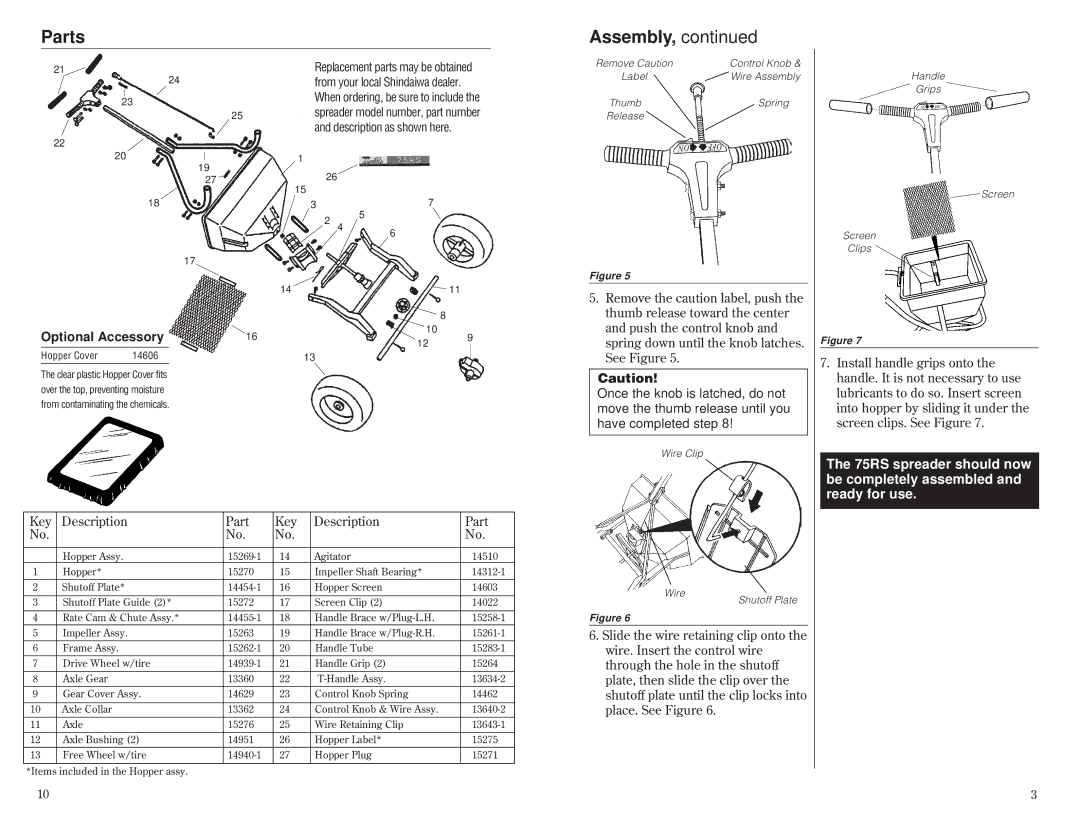
75RS, 80045 specifications
The Shindaiwa 75RS,80045 is a highly regarded trimmer known for its robust performance and advanced features that cater to both professional landscapers and home garden enthusiasts. This model stands out due to its efficient and powerful engine, ergonomic design, and innovative technologies that make yard work more manageable and enjoyable.At the heart of the 75RS,80045 lies a well-engineered 75cc engine that ensures reliable power delivery. This potent engine enables the trimmer to tackle thick grass, weeds, and underbrush with ease, making it suitable for various landscaping tasks. The engine is designed for fuel efficiency, allowing operators to work longer without frequent refueling. Additionally, it employs advanced low-emission technology, complying with stringent environmental standards while maintaining high performance.
One of the key features of the Shindaiwa 75RS,80045 is its ergonomic design. The handle is thoughtfully constructed to reduce operator fatigue, allowing for extended use without discomfort. The trimmer's balance and lightweight construction further enhance maneuverability, making it easy to navigate through tight spaces and around obstacles. This focus on user comfort ensures that both professional landscapers and hobbyists can operate the equipment efficiently.
The 75RS,80045 also incorporates innovative technologies to improve functionality. The Easy Start system significantly reduces the effort required to start the engine, allowing users to get to work quickly. Moreover, the advanced cutting system features durable and interchangeable cutting heads, enhancing versatility and performance. This adaptability makes it possible to switch between tasks, whether it's trimming, edging, or clearing brush.
Another noteworthy characteristic is the trimmer’s robust build quality. Constructed from high-grade materials, the Shindaiwa 75RS,80045 is designed to withstand harsh outdoor conditions, ensuring durability and longevity. This resilience means that it can handle the rigors of professional use while maintaining peak performance over time.
In summary, the Shindaiwa 75RS,80045 is a top-tier trimmer that combines exceptional performance, user-friendly features, and durable construction. Whether for commercial landscaping or personal use, this model is engineered to meet the demands of any user, making yard maintenance not just easier, but also more effective. Its blend of power, efficiency, and comfort makes it a valuable addition to any lawn care toolset.

