Introduction |
| Prepare to Assemble |
This manual contains information for the proper assembly, operation and care of your SP210 sprayer. Carefully read and follow the instructions contained in this manual before operat- ing your sprayer.
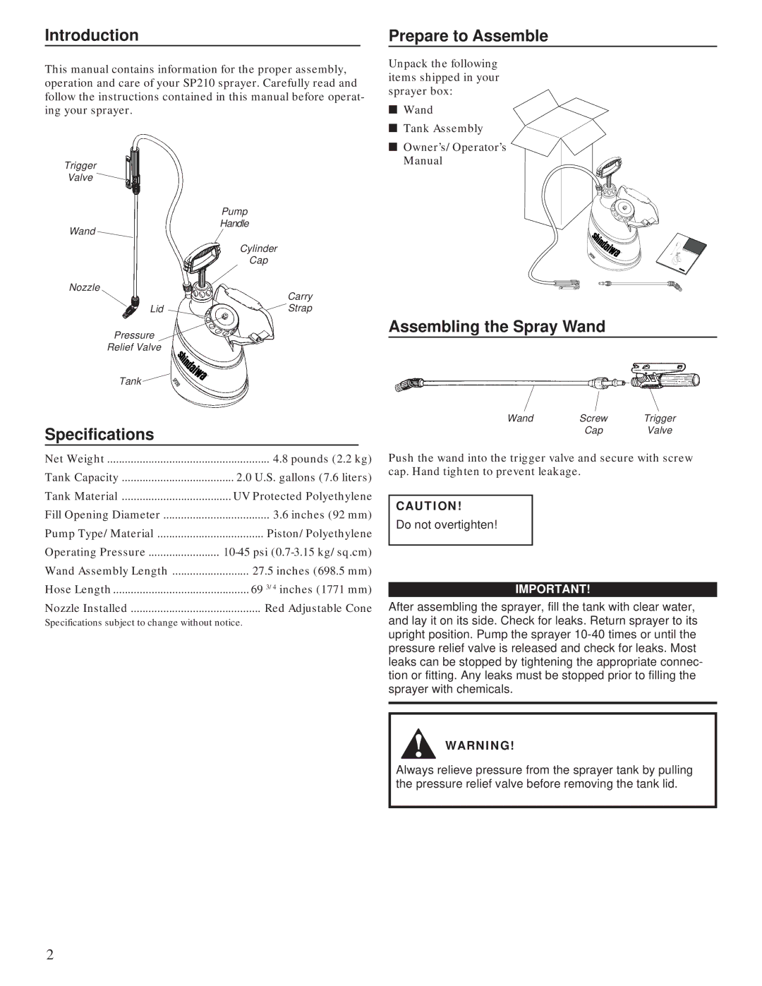
Trigger
Valve
Pump
Handle
Wand
Cylinder
Cap
Nozzle
| Carry |
Lid | Strap |
Pressure
Relief Valve
Unpack the following items shipped in your sprayer box:
■Wand
■ Tank Assembly
■Owner’s/Operator’s Manual
®
Assembling the Spray Wand
® Tank ![]()
Specifications
Net Weight | 4.8 pounds (2.2 kg) |
Tank Capacity | 2.0 U.S. gallons (7.6 liters) |
Tank Material | UV Protected Polyethylene |
Fill Opening Diameter | 3.6 inches (92 mm) |
Pump Type/Material | Piston/Polyethylene |
Operating Pressure | |
Wand Assembly Length | 27.5 inches (698.5 mm) |
Hose Length | 69 3/4 inches (1771 mm) |
Nozzle Installed | Red Adjustable Cone |
Specifications subject to change without notice.
Wand | Screw | Trigger |
| Cap | Valve |
Push the wand into the trigger valve and secure with screw cap. Hand tighten to prevent leakage.
CAUTION!
Do not overtighten!
IMPORTANT!
After assembling the sprayer, fill the tank with clear water, and lay it on its side. Check for leaks. Return sprayer to its upright position. Pump the sprayer
WARNING!
Always relieve pressure from the sprayer tank by pulling the pressure relief valve before removing the tank lid.
2