5.Remove the two screws securing the present switch stack and carefully move the switch stack to one side. Attach
the
6.Assemble the
7.Perforate the LUBRIPLATE capsule and apply the lubricant where the Monitor switch bar touches the Monitor switch, and where the Transmit switch bar touches the Transmit switch.
8.Solder the cartridge, cable and associated circuitry leads to the switch stack terminals as required (see Wiring section).
9.Bend or ªknifeº the Monitorand Transmit switch blades as required to make proper contact in the desired sequence.
10.Replace the baseplate and fasten it with the screws previously removed.
11.Remove the paper backing from the Monitor and Transmit labels and affix them on or adjacent to the Monitor and Transmit switch bars.
WIRING
Refer to the transceiver and microphone data sheets, and wire the microphone for the desired functions. Note that wiring for open or shorted squelch and transmit circuits can be employed. In the three wiring examples that follow, the
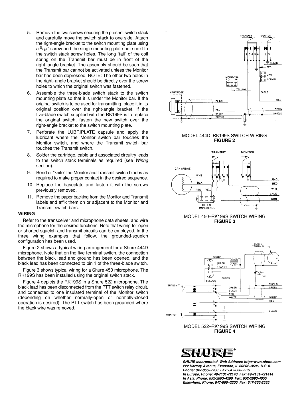
Figure 2 shows a typical wiring arrangement for a Shure 444D microphone. Note that on the five-terminal switch, the connection between the black lead and ground has been opened, and the black lead has been connected to pin 1 of the three-blade switch.
Figure 3 shows typical wiring for a Shure 450 microphone. The RK199S has been installed using the original switch stack.
Figure 4 depicts the RK199S in a Shure 522 microphone. The black lead has been disconnected from the PTT switch relay circuit, and connected to one insulated terminal of the Monitor switch (depending on whether normally-open or normally-closed operation is desired). The PTT switch has been grounded where the black wire was removed.
MODEL 444D±RK199S SWITCH WIRING
FIGURE 2
MODEL 450±RK199S SWITCH WIRING
FIGURE 3
MODEL 522±RK199S SWITCH WIRING
FIGURE 4
SHURE Incorporated Web Address: http://www.shure.com 222 Hartrey Avenue, Evanston, IL 60202±3696, U.S.A. Phone:
In Europe, Phone:
In Asia, Phone:
Elsewhere, Phone: