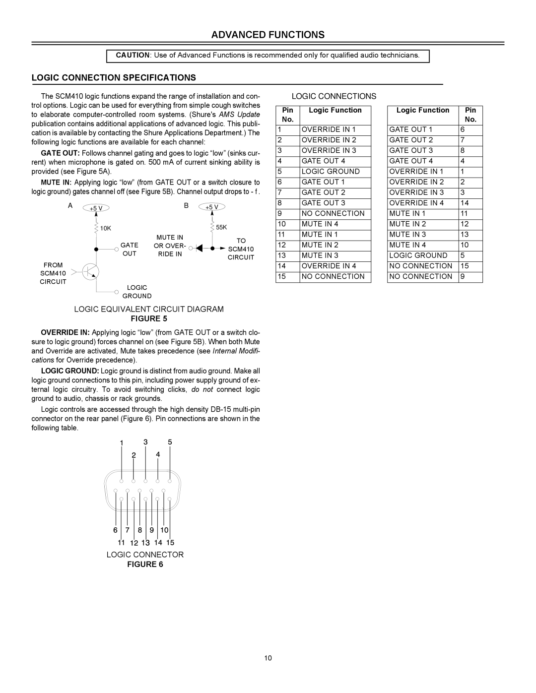
SCM410E, SCM410 specifications
The Shure SCM410 and SCM410E are state-of-the-art automatic microphone mixers designed to enhance audio performance in various professional environments. Known for their reliability and advanced features, these mixers are a popular choice for broadcasters, conferencing systems, and live event productions.One of the key features of the SCM410 is its Automatic Gain Control (AGC) system, which intelligently adjusts the gain of connected microphones based on their audio levels. This ensures that the output remains consistent, making it ideal for situations where multiple speakers might share the microphone, such as panel discussions or meetings. The SCM410E variant further enhances this functionality with extended connectivity options, catering to more complex audio setups.
Both models incorporate Shure's exclusive IntelliMix technology. IntelliMix employs sophisticated algorithms to minimize interference and eliminate feedback, which is crucial for maintaining intelligibility in crowded sound environments. The mixers automatically manage the microphone levels, activating only those that are in use while suppressing those that are not, which not only enhances audio clarity but also helps in reducing background noise.
The SCM410 features four microphone inputs, allowing operators to connect multiple microphones simultaneously. Users can easily control each input's level, with individual gain adjustments and a master output level control. Additionally, LEDs provide visual feedback on the status of each microphone, indicating when they are active or inactive. The SCM410E goes a step further, offering additional mic input options and enhanced flexibility for integration into larger systems.
Durability is a hallmark of the SCM410 and SCM410E, as they are constructed with high-quality materials, designed to withstand the rigors of professional use. The intuitive interface makes them accessible for both novice users and seasoned sound engineers.
With a phantom power switch for condenser microphones, an easy-to-read, backlit display, and robust connectivity options, the SCM410 and SCM410E are versatile tools for any audio setup. Their ability to automatically mix and control audio levels in real-time ensures that users can deliver presentations, discussions, and performances with clarity and confidence. Whether it’s in a corporate boardroom or a live concert venue, these automatic microphone mixers deliver high-quality sound tailored to the needs of modern audio applications.

