User Manual SICLOCK DCFRS Industrial Version
2.3.3 Assembly of the Antenna Frame
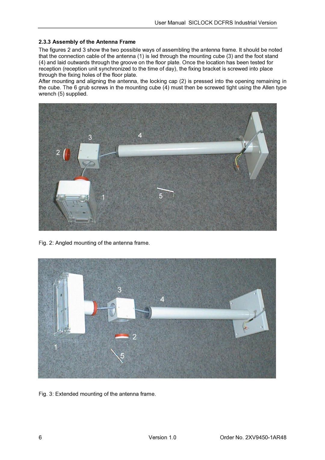
The figures 2 and 3 show the two possible ways of assembling the antenna frame. It should be noted that the connection cable of the antenna (1) is led through the mounting cube (3) and the foot stand
(4)and laid outwards through the groove on the floor plate. Once the location has been tested for reception (reception unit synchronized to the time of day), the fixing bracket is screwed into place through the fixing holes of the floor plate.
After mounting and aligning the antenna, the locking cap (2) is pressed into the opening remaining in the cube. The 6 grub screws in the mounting cube (4) must then be screwed tight using the Allen type wrench (5) supplied.
Fig. 2: Angled mounting of the antenna frame.
Fig. 3: Extended mounting of the antenna frame.
6 | Version 1.0 | Order No. |