User Manual SICLOCK GPS1000

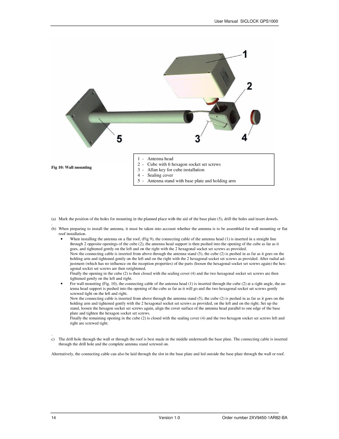
Fig 10: Wall mounting

1 - Antenna head

2 - Cube with 6 hexagon socket set screws

3- Allan key for cube installation

4 - Sealing cover

5 - Antenna stand with base plate and holding arm

(a)Mark the position of the holes for mounting in the planned place with the aid of the base plate (5), drill the holes and insert dowels.

.

(b)When preparing to install the antenna, it must be taken into account whether the antenna is to be assembled for wall mounting or flat roof installation.

When installing the antenna on a flat roof, (Fig 9), the connecting cable of the antenna head (1) is inserted in a straight line through 2 opposite openings of the cube (2), the antenna head support is then pushed into the opening of the cube as far as it goes, and tightened gently on the left and on the right with the 2 hexagonal socket set screws as provided.

Now the connecting cable is inserted from above through the antenna stand (5), the cube (2) is pushed in as far as it goes on the holding arm and tightened gently on the left and on the right with the 2 hexagonal socket set screws as provided. After radial ad- justment (which has no influence on the reception properties) of the parts (loosen the hexagonal socket set screws again) the hex- agonal socket set screws are then retightened.

Finally the opening in the cube (2) is then closed with the sealing cover (4) and the two hexagonal socket set screws are then tightened gently on the left and right.

For wall mounting (Fig. 10), the connecting cable of the antenna head (1) is inserted through the cube (2) at a right angle, the an- tenna head support is pushed into the opening of the cube as far as it will go and the two hexagonal socket set screws gently screwed tight on the left and right.

Now the connecting cable is inserted from above through the antenna stand (5), the cube (2) is pushed in as far as it goes on the holding arm and tightened gently with the 2 hexagonal socket set screws as provided, on the left and on the right. Set up the stand, loosen the hexagon socket set screws again, align the cover surface of the antenna head parallel to one edge of the base plate and tighten the hexagon socket set screws.

Finally the remaining opening in the cube (2) is closed with the sealing cover (4) and the two hexagon socket set screws left and right are screwed tight.

.

c)The drill hole through the wall or through the roof is best made in the middle underneath the base plate. The connecting cable is inserted through the drill hole and the complete antenna stand screwed on.

Alternatively, the connecting cable can also be laid through the slot in the base plate and led outside the base plate through the wall or roof.

14

Version 1.0

Order number 2XV9450-1AR82-BA

Page 32
Image 32
Siemens 2XV9450-1AR82 user manual Wall mounting

2XV9450-1AR82 specifications

The Siemens 2XV9450-1AR82 is a versatile component designed for various industrial applications, known for its reliability and efficiency. Part of Siemens’ extensive portfolio, this device plays a critical role in optimizing system performance and ensuring sustainable operations in numerous environments.

One of the main features of the 2XV9450-1AR82 is its ability to function under diverse conditions while maintaining high operational efficiency. This component is engineered to operate at a wide temperature range, allowing it to perform reliably in both extreme heat and cold without compromising on functionality.

The technology utilized in the Siemens 2XV9450-1AR82 includes advanced electronic circuitry that enhances its performance capabilities. This feature enables seamless integration with other components in a system, promoting coordinated operations and enhanced reliability. Moreover, the use of state-of-the-art materials in its construction ensures durability, contributing to its longevity and low maintenance costs.

Another significant characteristic of the 2XV9450-1AR82 is its energy efficiency. In an era where energy conservation is critical for both environmental and economic reasons, this component is designed to minimize energy consumption. This not only reduces operational costs but also helps companies meet sustainability goals, making it an attractive option for businesses focused on minimizing their ecological footprint.

The flexibility of the Siemens 2XV9450-1AR82 allows it to be used in a variety of sectors, including manufacturing, transportation, and energy management. Its adaptability means that it can meet the specific needs of different industries, thereby enhancing operational effectiveness across various applications.

Additionally, the built-in diagnostic features of the 2XV9450-1AR82 provide users with essential information regarding performance status and potential issues. This proactive approach to maintenance ensures that potential problems are addressed before they escalate, reducing downtime and improving overall productivity.

In summary, the Siemens 2XV9450-1AR82 stands out for its robust features, advanced technology, and efficiency, making it an invaluable asset in modern industrial applications. Its ability to adapt to various environments and its focus on energy savings reflect Siemens' commitment to innovation and sustainable development in the industry. As industries continue to evolve, the Siemens 2XV9450-1AR82 remains a key component in driving progress and enhancing operational capabilities.