User Manual SICLOCK GPS1000
3.2. Connection to SICLOCK TC400 / TC100 or TS
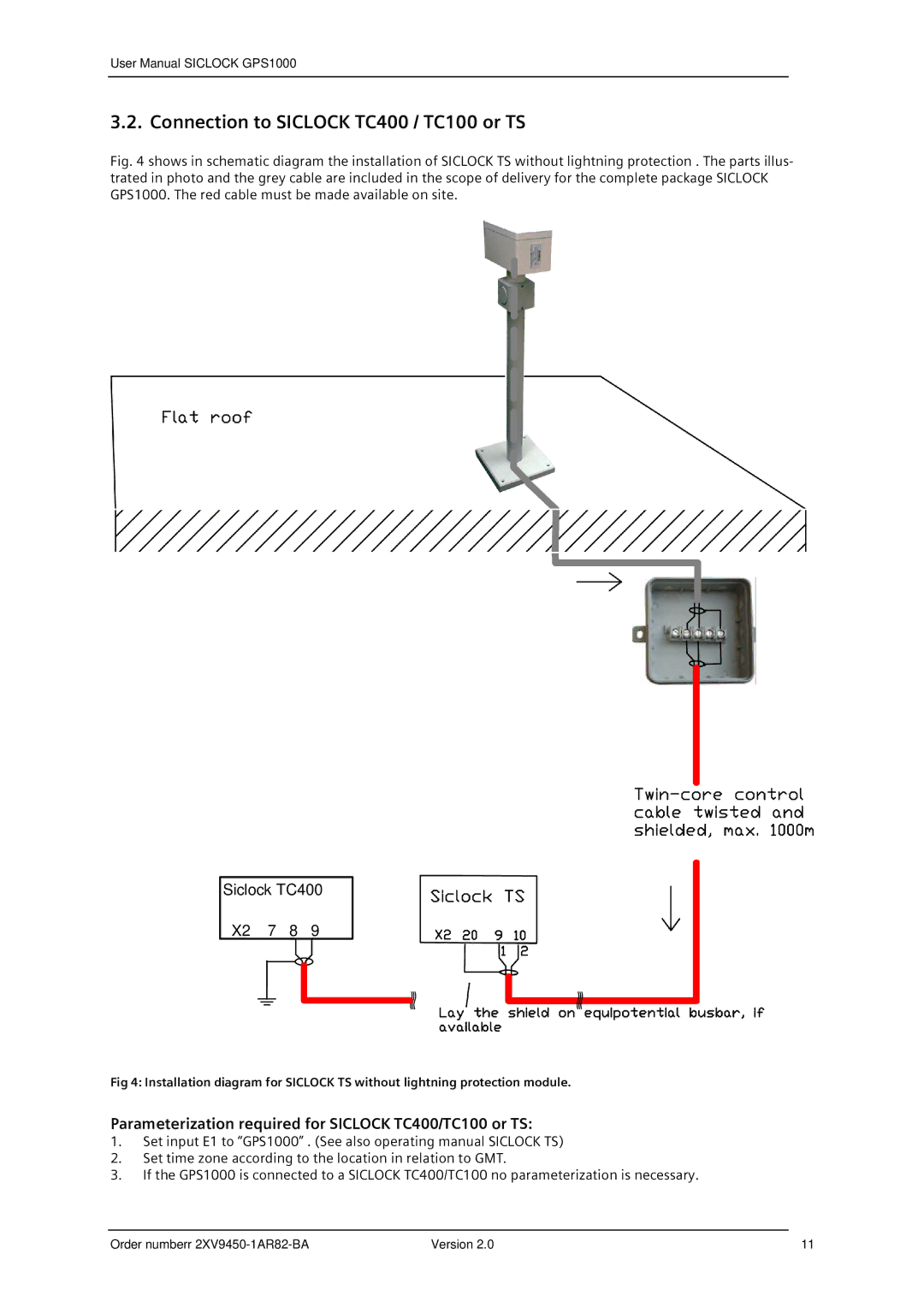
Fig. 4 shows in schematic diagram the installation of SICLOCK TS without lightning protection . The parts illus- trated in photo and the grey cable are included in the scope of delivery for the complete package SICLOCK GPS1000. The red cable must be made available on site.
Siclock TC400
X2 7 8 9
Fig 4: Installation diagram for SICLOCK TS without lightning protection module.
Parameterization required for SICLOCK TC400/TC100 or TS:
1.Set input E1 to “GPS1000” . (See also operating manual SICLOCK TS)
2.Set time zone according to the location in relation to GMT.
3.If the GPS1000 is connected to a SICLOCK TC400/TC100 no parameterization is necessary.
Order numberr | Version 2.0 | 11 |