GCX Mounting Assembly Operation/Installation Manual
Dräger Model Cato ® with Siemens SC9000 Patient Monitor
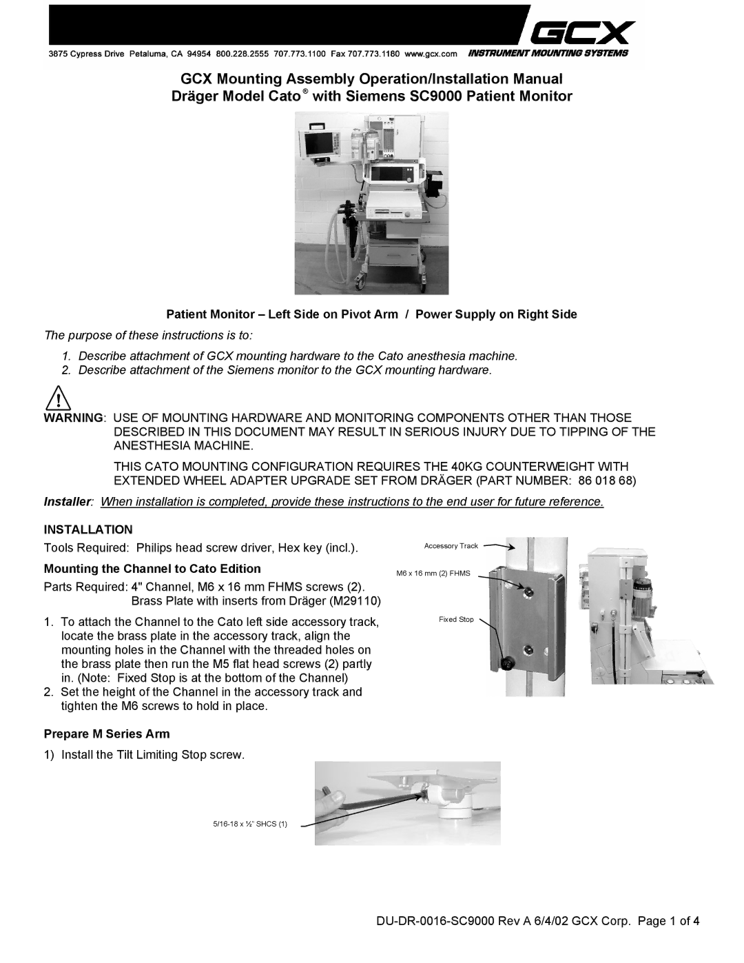
Patient Monitor – Left Side on Pivot Arm / Power Supply on Right Side
The purpose of these instructions is to:
1.Describe attachment of GCX mounting hardware to the Cato anesthesia machine.
2.Describe attachment of the Siemens monitor to the GCX mounting hardware.
WARNING: USE OF MOUNTING HARDWARE AND MONITORING COMPONENTS OTHER THAN THOSE DESCRIBED IN THIS DOCUMENT MAY RESULT IN SERIOUS INJURY DUE TO TIPPING OF THE ANESTHESIA MACHINE.
THIS CATO MOUNTING CONFIGURATION REQUIRES THE 40KG COUNTERWEIGHT WITH EXTENDED WHEEL ADAPTER UPGRADE SET FROM DRÄGER (PART NUMBER: 86 018 68)
Installer: When installation is completed, provide these instructions to the end user for future reference.
INSTALLATION
Tools Required: Philips head screw driver, Hex key (incl.).
Mounting the Channel to Cato Edition
Parts Required: 4" Channel, M6 x 16 mm FHMS screws (2). Brass Plate with inserts from Dräger (M29110)
1.To attach the Channel to the Cato left side accessory track, locate the brass plate in the accessory track, align the mounting holes in the Channel with the threaded holes on the brass plate then run the M5 flat head screws (2) partly in. (Note: Fixed Stop is at the bottom of the Channel)
2.Set the height of the Channel in the accessory track and tighten the M6 screws to hold in place.
Prepare M Series Arm
1) Install the Tilt Limiting Stop screw.
Accessory Track
M6 x 16 mm (2) FHMS
Fixed Stop