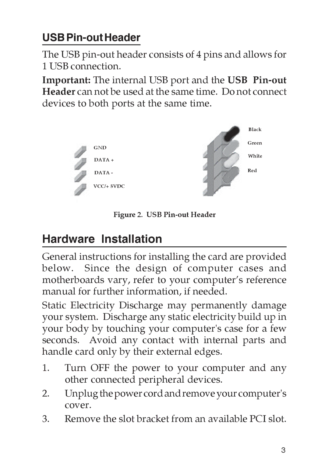
USB Pin-out Header
The USB
Important: The internal USB port and the USB
| Black |
GND | Green |
| |
DATA + | White |
| |
DATA - | Red |
| |
VCC/+ 5VDC |
|
Figure 2. USB Pin-out Header
Hardware Installation
General instructions for installing the card are provided below. Since the design of computer cases and motherboards vary, refer to your computer’s reference manual for further information, if needed.
Static Electricity Discharge may permanently damage your system. Discharge any static electricity build up in your body by touching your computer's case for a few seconds. Avoid any contact with internal parts and handle card only by their external edges.
1.Turn OFF the power to your computer and any other connected peripheral devices.
2.Unplug the power cord and remove your computer's cover.
3.Remove the slot bracket from an available PCI slot.
3