Silicon Laboratories Contents, ToolStick Debug Adapter Specifications, Pin #, Description

Models: Debug Adapter

1 6
Download 6 pages 2.08 Kb
Page 2
Image 2
ToolStick Debug Adapter

ToolStick Debug Adapter

2. Contents

The ToolStick Debug Adapter package contains the following items:

„ToolStick Debug Adapter (USB to Debug Interface)

„7” Ribbon Cable

Note: The ToolStick Debug Adapter requires a ToolStick Base Adapter for proper operation.

3. ToolStick Debug Adapter Specifications

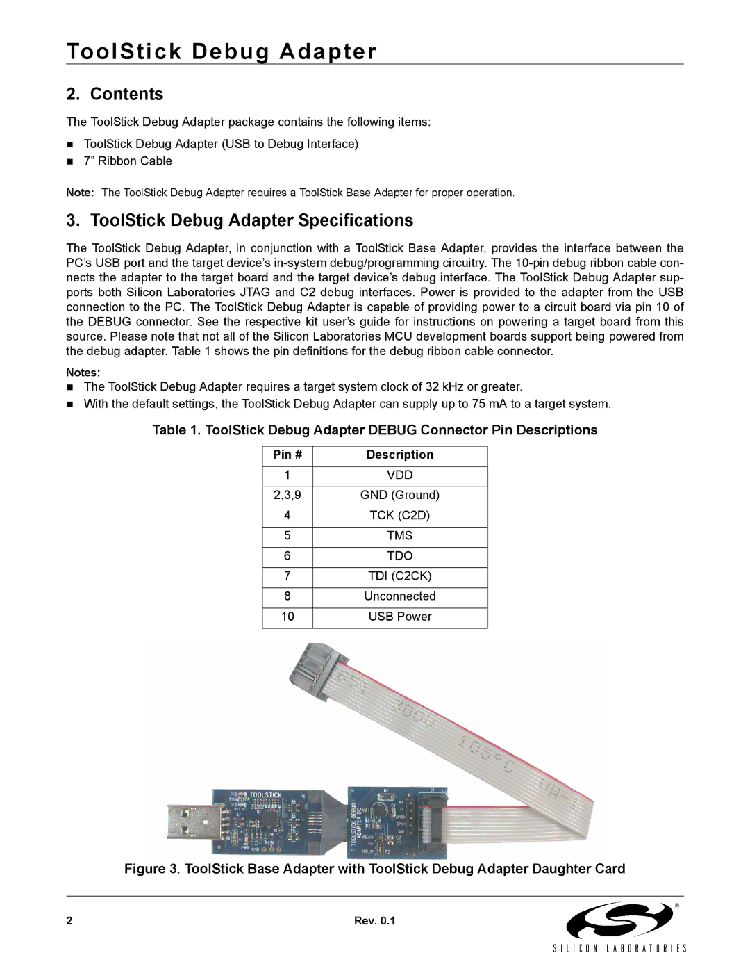
The ToolStick Debug Adapter, in conjunction with a ToolStick Base Adapter, provides the interface between the PC’s USB port and the target device’s in-system debug/programming circuitry. The 10-pin debug ribbon cable con- nects the adapter to the target board and the target device’s debug interface. The ToolStick Debug Adapter sup- ports both Silicon Laboratories JTAG and C2 debug interfaces. Power is provided to the adapter from the USB connection to the PC. The ToolStick Debug Adapter is capable of providing power to a circuit board via pin 10 of the DEBUG connector. See the respective kit user’s guide for instructions on powering a target board from this source. Please note that not all of the Silicon Laboratories MCU development boards support being powered from the debug adapter. Table 1 shows the pin definitions for the debug ribbon cable connector.

Notes:

„The ToolStick Debug Adapter requires a target system clock of 32 kHz or greater.

„With the default settings, the ToolStick Debug Adapter can supply up to 75 mA to a target system.

Table 1. ToolStick Debug Adapter DEBUG Connector Pin Descriptions

Pin #
Description


1

VDD


2,3,9

GND (Ground)


4

TCK (C2D)


5

TMS


6

TDO


7

TDI (C2CK)


8

Unconnected


10

USB Power


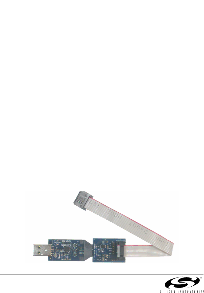
Figure 3. ToolStick Base Adapter with ToolStick Debug Adapter Daughter Card

2

Rev. 0.1

Page 2
Image 2
Silicon Laboratories manual Contents, ToolStick Debug Adapter Specifications, Pin #, Description