Installation
Needed for Installation (not included)
Mounting hardware for the inverter
Tools
Mounting
Step #1: The
CAUTION: The power inverter must be mounted securely in any type of moving vehicle. In an emergency situation, if the power inverter is not securely mounted, it could cause bodily injury
Connection to Power Source
The
Do not use a 12V extension cord with this unit.
Testing the Power Inverter
Make sure the 12 volt power source is wired properly to the power inverter. With nothing plugged into the 115 VAC outlets, turn on the power switch of the
If the green power light does not come on, turn the power switch off and check your wiring and external fuse.
With the inverter turned off, plug the appliance you want to use into the 115 VAC power outlet on the unit. Turn on the power switch of the STP- 150. The appliance should now be operational.
Operation
Equipment Power Usage
It is important to use only products that draw less than 150 watts with the
How to calculate power usage.
Most products have a power rating on them such as 45 watts. Others may be marked with their current draw, such as .9 amps. To convert the current to watts multiply the current by 115. Thus .9 amps x 115 = 104 watts.
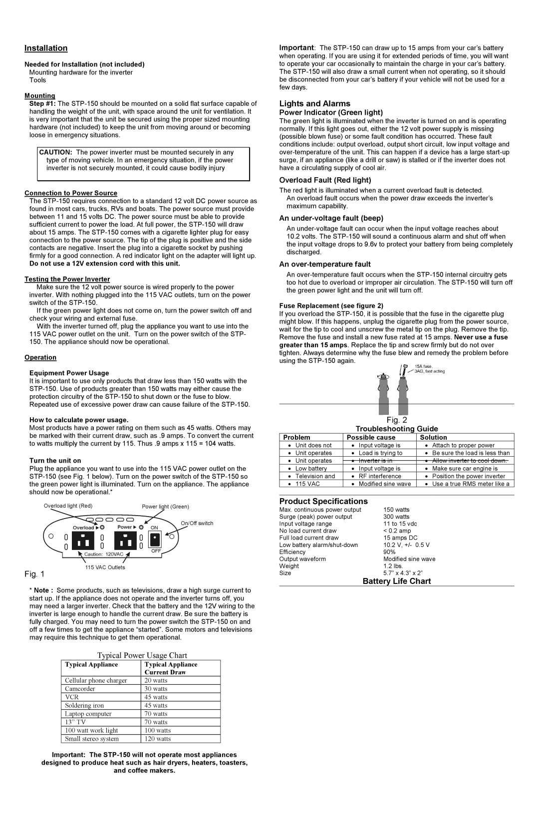
Turn the unit on
Plug the appliance you want to use into the 115 VAC power outlet on the
Fig. 1
*Note : Some products, such as televisions, draw a high surge current to start up. If the appliance does not operate and the inverter turns off, you may need a larger inverter. Check that the battery and the 12V wiring to the inverter is large enough to handle the current draw. Be sure the battery is fully charged. You may need to turn the power switch the
Typical Power Usage Chart
Typical Appliance | Typical Appliance |
| Current Draw |
Cellular phone charger | 20 watts |
Camcorder | 30 watts |
VCR | 45 watts |
Soldering iron | 45 watts |
Laptop computer | 70 watts |
13” TV | 70 watts |
100 watt work light | 100 watts |
Small stereo system | 120 watts |
Important: The
designed to produce heat such as hair dryers, heaters, toasters,
and coffee makers.
Important: The
Lights and Alarms
Power Indicator (Green light)
The green light is illuminated when the inverter is turned on and is operating normally. If this light goes out, either the 12 volt power supply is missing (possible blown fuse) or some fault condition has occurred. These fault conditions include: output overload, output short circuit, low input voltage and
Overload Fault (Red light)
The red light is illuminated when a current overload fault is detected. An overload fault occurs when the power draw exceeds the inverter’s maximum capability.
An under-voltage fault (beep)
An
10.2volts. The
An over-temperature fault
An
Fuse Replacement (see figure 2)
If you overload the
Fig. 2
Troubleshooting Guide
Problem | Possible cause | Solution | ||
• | Unit does not | • | Input voltage is | • Attach to proper power |
• | Unit operates | • Load is trying to | • Be sure the load is less than | |
• | Unit operates | • | Inverter is in | • Allow inverter to cool down. |
• | Low battery | • | Input voltage is | • Make sure car engine is |
• | Television and | • | RF interference | • Position the power inverter |
• | 115 VAC | • | Modified sine wave | • Use a true RMS meter like a |
Product Specifications
Max. continuous power output | 150 watts |
Surge (peak) power output | 300 watts |
Input voltage range | 11 to 15 vdc |
No load current draw | < 0.2 amp |
Full load current draw | 15 amps DC |
Low battery | 10.2 V, +/- 0.5 V |
Efficiency | 90% |
Output waveform | Modified sine wave |
Weight | 1.2 lbs. |
Size | 5.7” x 4.3” x 2” |