AURORA specifications
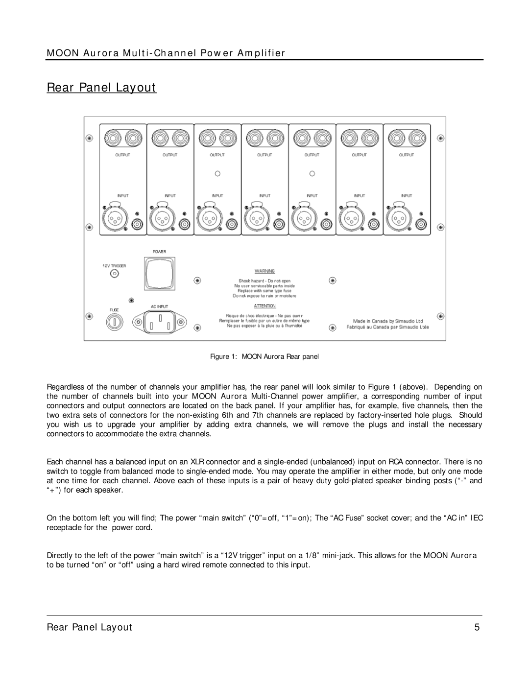
Simaudio AURORA is a premium audio component line designed to deliver an exceptional listening experience through advanced engineering and innovative technologies. Manufactured by Simaudio, a well-respected name in high-fidelity audio, AURORA components are crafted to meet the demands of audiophiles and music enthusiasts alike.One of the main features of the AURORA series is its commitment to high-resolution audio playback. The components are designed to support a wide range of audio formats, including high-definition digital formats, ensuring that users can enjoy their music in the best possible quality. The AURORA series incorporates cutting-edge DAC technology that minimizes distortion and maximizes clarity, enabling a more faithful reproduction of the original audio source.
The AURORA line is characterized by its sleek and modern design, which not only looks sophisticated but also allows for optimal heat dissipation. This ensures that the components maintain their performance under continuous use. Simaudio pays close attention to the materials and build quality, using robust enclosures that minimize vibration and external interference, further enhancing audio performance.
One notable technology featured in the AURORA series is the Moon Eclipse technology, which is designed to provide a balanced sound stage with precise imaging. This technology employs sophisticated signal processing to ensure that each audio element is accurately placed in the sound field, creating a lifelike listening experience. Furthermore, AURORA components are equipped with proprietary power supplies that deliver stable and clean power to the circuits, reducing noise and improving overall performance.
User-friendliness is also a hallmark of the AURORA line. The components feature intuitive controls and interfaces, allowing users to easily navigate their music libraries and settings. Connectivity options are comprehensive, with support for digital inputs, analog connections, and Bluetooth streaming, catering to a variety of sources.
In summary, Simaudio AURORA represents the pinnacle of audio excellence, combining innovative technologies, premium materials, and user-friendly designs. With its focus on high-resolution audio playback, balanced sound stage, and robust construction, the AURORA series embodies Simaudio’s dedication to creating products that elevate the listening experience for all music lovers.

