Hardware Identification & Torque Specifications

Common Hardware Types

Hex Head Capscrew

Washer


Lockwasher

Carriage Bolt


Hex Nut

Standard Hardware Sizing

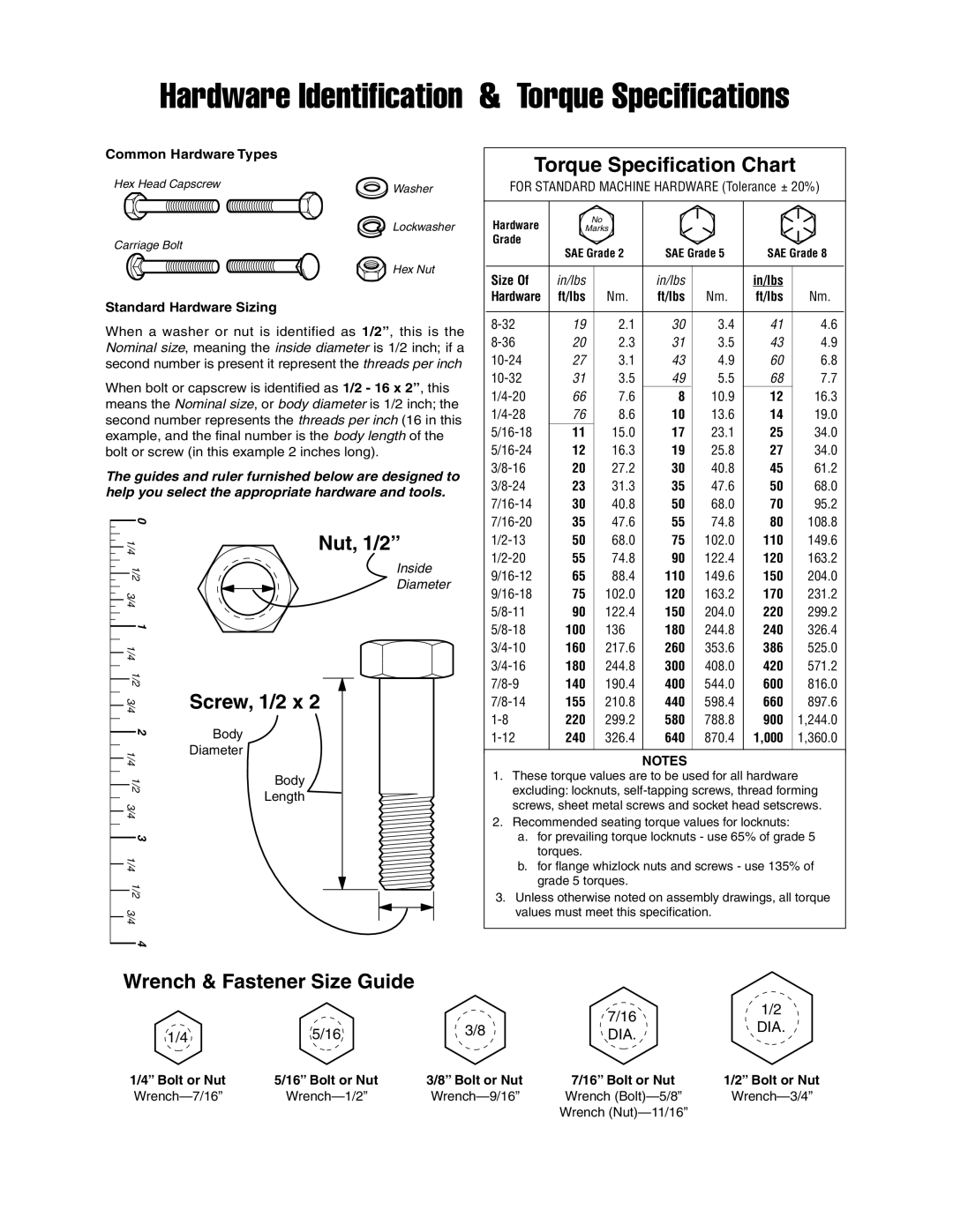
When a washer or nut is identified as 1/2”, this is the Nominal size, meaning the inside diameter is 1/2 inch; if a second number is present it represent the threads per inch

When bolt or capscrew is identified as 1/2 - 16 x 2”, this means the Nominal size, or body diameter is 1/2 inch; the second number represents the threads per inch (16 in this example, and the final number is the body length of the bolt or screw (in this example 2 inches long).

The guides and ruler furnished below are designed to help you select the appropriate hardware and tools.

0


1/4

Nut, 1/2”

1/2

Inside

Diameter

3/4


1


1/4


1/2


3/4

Screw, 1/2 x 2

2

Body


1/4

Diameter


1/2

Body

Length

3/4


3


1/4


1/2


3/4


4


Torque Specification Chart

FOR STANDARD MACHINE HARDWARE (Tolerance ± 20%)


Hardware


No


Marks


Grade

SAE Grade 2

SAE Grade 5

SAE Grade 8


Size Of

in/lbs


in/lbs


in/lbs


Hardware

ft/lbs


Nm.

ft/lbs

Nm.

ft/lbs


Nm.


8-32


19


2.1

30

3.4


41

4.6


8-36


20


2.3

31

3.5


43

4.9


10-24


27


3.1

43

4.9


60

6.8


10-32


31


3.5

49

5.5


68


7.7


1/4-20


66


7.6

8

10.9


12

16.3


1/4-28


76


8.6

10

13.6


14

19.0


5/16-18


11


15.0

17

23.1


25

34.0


5/16-24


12


16.3

19

25.8


27

34.0


3/8-16


20


27.2

30

40.8


45

61.2


3/8-24


23


31.3

35

47.6


50

68.0


7/16-14


30


40.8

50

68.0


70

95.2


7/16-20


35


47.6

55

74.8


80

108.8


1/2-13


50


68.0

75

102.0


110

149.6


1/2-20


55


74.8

90

122.4


120

163.2


9/16-12


65


88.4

110

149.6


150

204.0


9/16-18


75


102.0

120

163.2


170

231.2


5/8-11


90


122.4

150

204.0


220

299.2


5/8-18


100


136

180

244.8


240

326.4


3/4-10


160


217.6

260

353.6


386

525.0


3/4-16


180


244.8

300

408.0


420

571.2


7/8-9


140


190.4

400

544.0


600

816.0


7/8-14


155


210.8

440

598.4


660

897.6


1-8


220


299.2

580

788.8


900

1,244.0


1-12


240


326.4

640

870.4


1,000

1,360.0


NOTES

1.These torque values are to be used for all hardware excluding: locknuts, self-tapping screws, thread forming screws, sheet metal screws and socket head setscrews.

2.Recommended seating torque values for locknuts:

a.for prevailing torque locknuts - use 65% of grade 5 torques.

b.for flange whizlock nuts and screws - use 135% of grade 5 torques.

3.Unless otherwise noted on assembly drawings, all torque values must meet this specification.

Wrench & Fastener Size Guide


7/16

1/2


3/8

DIA.

1/4

5/16

DIA.


1/4” Bolt or Nut

5/16” Bolt or Nut

3/8” Bolt or Nut

7/16” Bolt or Nut

1/2” Bolt or Nut

Wrench—7/16”

Wrench—1/2”

Wrench—9/16”

Wrench (Bolt)—5/8”

Wrench—3/4”


Wrench (Nut)—11/16”


Page 15
Image 15
Simplicity 1695064, 1734817 manual Hardware Identification & Torque Specifications

1695064, 1734817 specifications

Simplicity 1734817 and Simplicity 1695064 are notable examples of electronic design automation (EDA) tools, developed with the objective of simplifying the design process for engineers in various industries. These innovative solutions cater to the growing demand for efficient design methodologies while reducing time-to-market for complex products.

One of the main features of Simplicity 1734817 is its intuitive user interface, which significantly enhances usability. Engineers can easily navigate through the software, identifying tools and functions without extensive training. The interface is designed to streamline the design workflow, allowing users to concentrate on the creative aspects of their projects.

In contrast, Simplicity 1695064 boasts advanced simulation capabilities that enable real-time analysis of designs. This feature allows engineers to verify their work as they progress, reducing errors and facilitating modifications on-the-fly. The simulation tools are particularly beneficial for those working in multiple domains, offering customizable parameters that cater to specific requirements.

Both models are equipped with state-of-the-art technologies that enhance performance. They utilize cloud-based computing, enabling users to access powerful processing capabilities without the need for high-end local hardware. This is especially advantageous for remote teams, as it fosters collaboration across different locations. Additionally, these tools utilize machine learning algorithms to suggest design optimizations, allowing for smarter decision-making during the design process.

Another significant characteristic of Simplicity 1734817 and 1695064 is their compatibility with various third-party applications. This flexibility ensures that engineers can incorporate their tools into existing workflows seamlessly, enhancing productivity without disrupting established processes. Moreover, robust support for multiple file formats simplifies collaboration with other team members or departments.

In summary, Simplicity 1734817 and Simplicity 1695064 deliver powerful features aimed at enhancing the design experience. With their user-friendly interfaces, advanced simulation capabilities, cloud integration, and compatibility with existing tools, they stand out as essential resources for engineers seeking efficiency and effectiveness in their design projects. These models exemplify the evolution of EDA tools in support of innovation and productivity across various industries.