Manuals
/
Simplicity
/
Lawn and Garden
/
Lawn Mower
Simplicity
5101604
manual
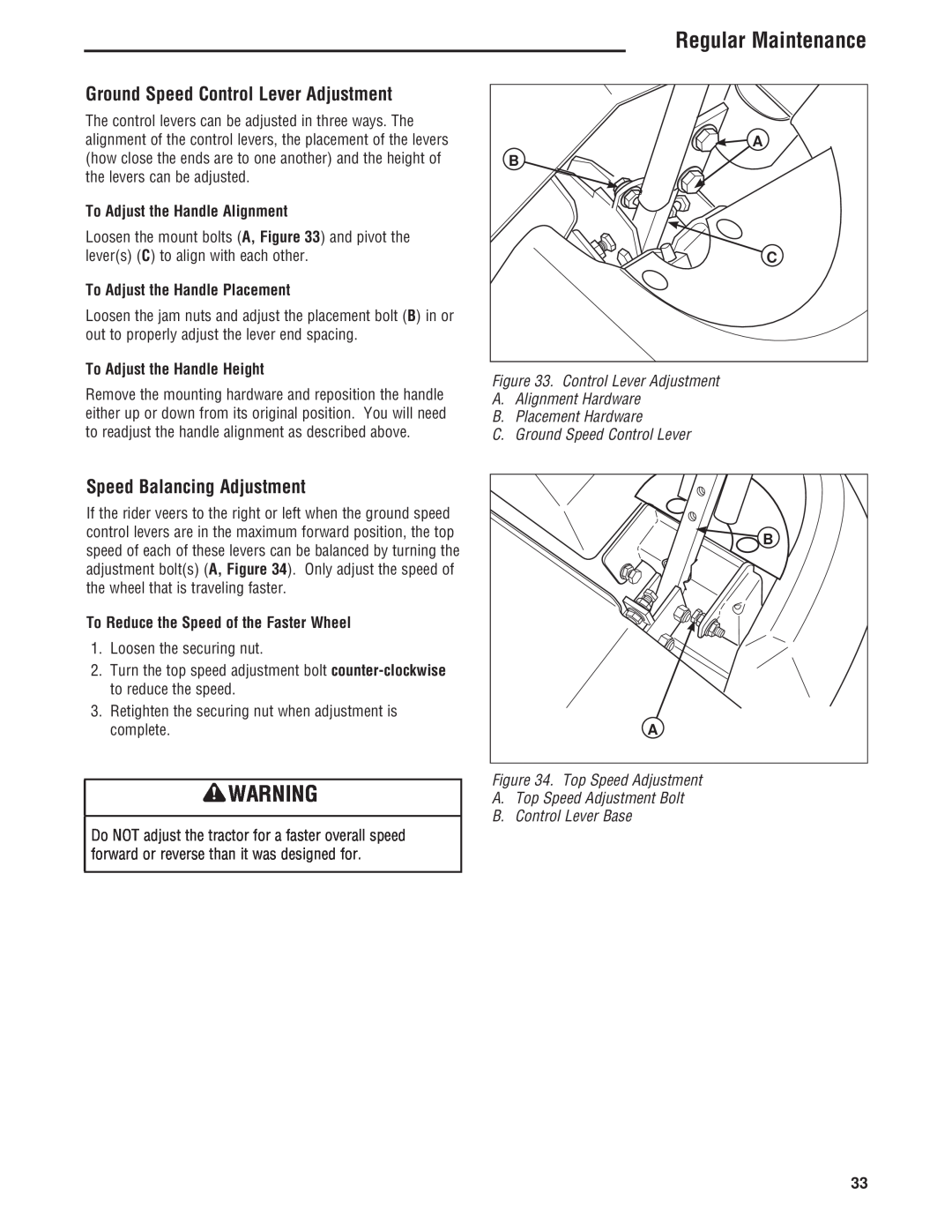
Ground Speed Control Lever Adjustment, Speed Balancing Adjustment
Models:
5101604
543777-0113-E1
1
35
48
48
Download
48 pages
56.48 Kb
32
33
34
35
36
37
38
39
Troubleshooting
Specifications
Install
Maintenance
Battery Charging
Seat Adjustment Lever
How to
Mower Belt Replacement
Safety
PTO Power Take Off Switch
Page 35
Image 35
Page 34
Page 36
Page 35
Image 35
Page 34
Page 36
Contents
Mfg. No
OPERATOR’S MANUAL
Cobalt Series
30HP Zero-Turn Riders
DATE PURCHASED
Regular Maintenance
Table of Contents
Operator Safety
Features & Controls
Read the Manual
Operator Safety
Operator Safety
Operating Safety
Moving Parts
Slope Operation
Thrown Objects
Overhead Obstacles
Roll Bar Use
Retaining Walls, Drop-offs, and Water
Enclosed Areas
Fuel and Maintenance
Transporting and Storage
General Operation
Operating on steep slopes can be dangerous
Towed Equipment Ride-On Units
Emissions
Ignition System
Safe Handling of Gasoline
Service and Maintenance
Service & Maintenance
Inspection of the Roll Bar Protective Structure
Roll Bar Instructions
Operational Warnings
INSPECT BUCKLE LATCH INSPECT WEBBING
Inspection and Maintenance of the Roll Bar Seat Belt
Safety Decals
North American Safety Icons
Safety Interlock System
Operational SAFETY Checks
Safety Icons
CE Models
Features and Controls
Features and Controls
Identification Numbers
Parking Brake
Deck Lift Pedal, Cutting Height Adjustment Pin & Deck Lift Lock Lever
PTO Power Take Off Switch
Control Functions
Throttle Control
Ignition Switch
Hour Meter / Maintenance Reminder
Seat Adjustment Lever
Checks Before Starting
General Operating Safety
Operation
Operation
Operation
Seat Adjustment
Check Tire Pressures
Pushing the Rider by Hand
Figure 5. Mowing Height Adjustment A. Cutting Height Adjustment Pin
Mowing Height Adjustment
Foot Pedal Adjustment
To Adjust Pedal Position
2. NOTE A warm engine may not require choking
Starting the Engine
Stopping the Rider
Figure 7. Move Control Levers Gradually
Zero-Turn Driving Practice
Basic Driving
Smooth Travel
Figure 11. Turning in Place
Advanced Driving
Practice Turning Around a Corner
Figure 10. Turning Around a Corner
Storage
Raise and Lower the Roll Bar
To Lower the Roll Bar
To Raise the Roll Bar
Figure 14. Proper Cutting Height
Mowing
Mowing Recommendations
Height of Grass
How Much Grass to Cut Off When Broadcasting
Mowing Methods
When and How Often to Mow
Note Always operate the engine at full throttle when mowing
Mulching Requires EXCELLENT Mowing Conditions
Attaching a Trailer
Figure 17. Trailer Weight Recommendations A. Clevis Pin B. Clip
Proper Mulching
Safety Items
Regular Maintenance
Regular Maintenance
Maintenance Schedule
Inspect Muffler and Spark Arrester
Checking / Adding Fuel
Fuel Filter
Change Oil & Filter
Figure 19. Checking Hydraulic Oil Level A. Hydraulic Oil Reservoir
Check Hydraulic Oil Level
Change Hydraulic Oil Filter
Change Interval Every 250 Hours Filter Part Number
Figure 21. Deck Lubrication
Lubrication
Grease
Lubricating the Front Casters
Inspecting the Mower Blades
Servicing The Mower Blades
Removing the Mower Blade
Avoid injury! Mower blades are sharp
Sharpening the Mower Blade
Reinstalling the Mower Blades
Figure 31. Tightening the Mower Blade for Installation
C. Mower Blade Air Lift Points Up For Installation
Cleaning the Battery and Cables
Battery Charging
Battery Maintenance
NOTE This unit is equipped with a maintenance-free BCIU1 battery
To Adjust the Handle Placement
Ground Speed Control Lever Adjustment
Speed Balancing Adjustment
To Adjust the Handle Alignment
Figure 35. Neutral Adjustment RH side shown A. Adjustment Linkage Rod
Neutral Adjustment
Return-to-Neutral Adjustment
Checking the Adjustment
Figure 38. Hydraulic Pump Drive Belt Replacement A. Pump Drive Belt
Parking Brake Adjustment
Hydraulic Pump Drive Belt Replacement
Figure 37. Parking Brake Adjustment A. Brake Spring B. Adjustment Nut
To adjust the upper mounting position Rear Shocks
Suspension Adjustment
To adjust the spring pre-load
Spring loaded components can kick back causing injury
9. To adjust the outer lift rod Refer to Figure
Deck Lift Rod Timing Adjustment
Checking the Deck Lift Rod Timing Adjustment
4. To adjust the inner lift rod Refer to Figure
NOTE Before adjusting the deck level, the deck lift rod
Deck Leveling Adjustment
Deck Lift Spring
Regular Maintenance
Figure 47. Mower PTO Belt Routing A. Spindle Pulley B. PTO Drive Belt
Mower Belt Replacement
Figure 46. Mower PTO Belt A. Idler Arm B. Stationary Idler Pulley
C. 1/2” Breaker Bar D. Spring
PROBLEM
Troubleshooting
Troubleshooting
Troubleshooting the Rider
Brake will not hold
Troubleshooting the Rider continued
Troubleshooting the Mower
Rider drive belt slips
Stepped Cutting
Troubleshooting Common Cutting Problems
Streaking
Scalping
Technical Manuals
Specifications
Specifications
DIMENSIONS
FOLD
LINE
ALONG APPROPRIATE DOTTED
ANGLE OF THE SLOPE
Page
BELTS AND BLADES
Product Quick Specs
Top
Page
Image
Contents