Auger Drive and Impeller Group
NOTE: Unless noted otherwise, | 985496 |
| |
use the standard hardware torque |
|
specification chart. |
|
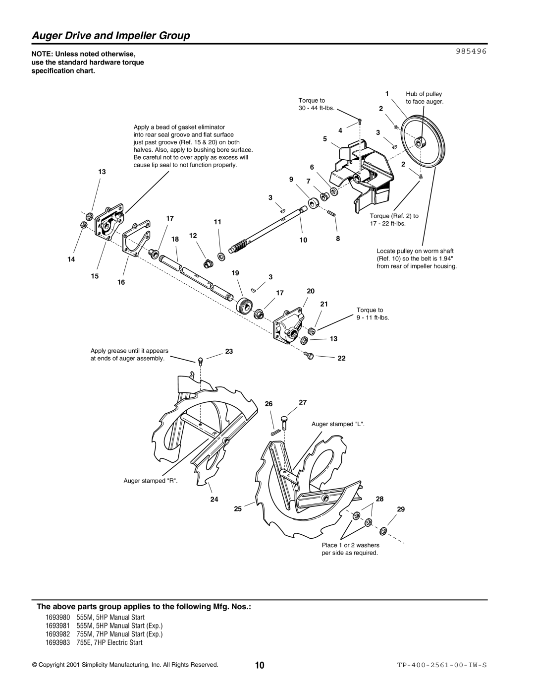
Apply a bead of gasket eliminator into rear seal groove and flat surface just past groove (Ref. 15 & 20) on both halves. Also, apply to bushing bore surface. Be careful not to over apply as excess will cause lip seal to not function properly.
13
Torque to
30 - 44
4 |
5 |
| 6 |
9 | 7 |
3
1 Hub of pulley to face auger.
2
3 |
2 |
14 |
17 | 11 |
| |
18 | 12 |
|
10 | 8 |
Torque (Ref. 2) to 17 - 22
Locate pulley on worm shaft (Ref. 10) so the belt is 1.94" from rear of impeller housing.
15 |
16 |
3
17 | 20 |
21
Torque to
9 - 11
13
Apply grease until it appears | 23 |
at ends of auger assembly. |
|
22
26 | 27 |
Auger stamped "L".
Auger stamped "R".
24 |
| 28 |
25 | 29 |
Place 1 or 2 washers per side as required.
The above parts group applies to the following Mfg. Nos.:
1693980 555M, 5HP Manual Start
1693981 555M, 5HP Manual Start (Exp.)
1693982 755M, 7HP Manual Start (Exp.)
1693983 755E, 7HP Electric Start
© Copyright 2001 Simplicity Manufacturing, Inc. All Rights Reserved. | 10 |