PERFORATING ONLY
If what you want is simply to make perforations in the material, you must place a new complete set of dies and make the following adjustments:
With the machine disconnected from the power source:
-Empty both the deposits and railings of any grommets and washers,
-Move the grommet railing to the left and secure it with a small puncher to the front raceway
bracket part nº 272 ,
-Next place the new complete set of dies and adjust the machine’s pressure.
-In the control panel “IMO V3” the washer detector switch must be set to the “0” position.
PLACEMENT LASER LIGHT (OPTIONAL ACCESSORIES)
-Your machine has an optional laser light that emits a red laser beam that can help with the placement of the grommet and washer.
-The machine includes a switch for this device, in the “IMO V3”. For connecting the switch see Electric installation.
Note: Although the light power of this laser is very small. DO NOT SHINE THIS LIGHT DIRECTLY IN ANYONE’S EYES SINCE IT COULD BE HARMFUL. KEEP IT AWAY FROM CHILDREN.
-For small grommets and washers, the machine may come with a little air pipe attached to the washer raceway, which blows the washer down onto their right position, by means of an air compressor.
-For placing grommets and washers in materials such as: canvas, sailcloth, etc, a small metallic tray may be attached to the machine, in order to be used as a base for the material.
-If you wish to know the amount of grommets and washers that you set each day, you can use a grommet and washer meter.
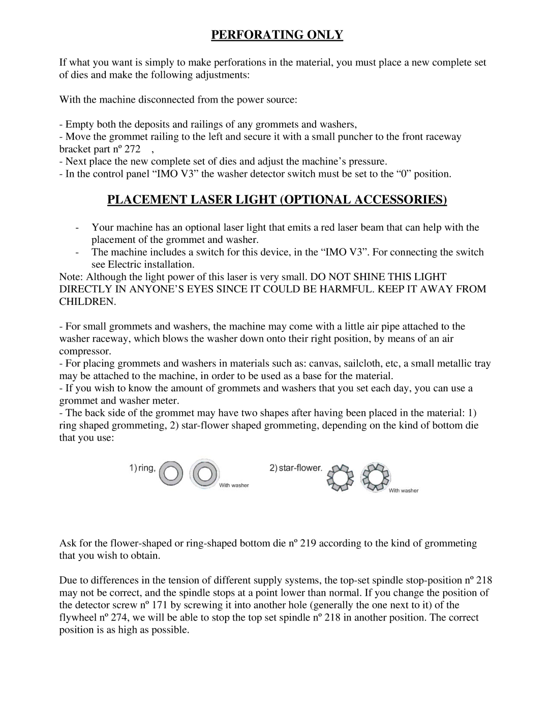
-The back side of the grommet may have two shapes after having been placed in the material: 1) ring shaped grommeting, 2)
Ask for the
Due to differences in the tension of different supply systems, the
