L-Series specifications
The Slant/Fin L-Series is a prominent line of hydronic baseboard heating products designed to provide efficient and reliable heating solutions for residential and commercial spaces. Renowned for their adaptability and performance, the L-Series units are particularly favored for their sleek design and exceptional heat transfer capabilities.One of the key features of the Slant/Fin L-Series is its low-profile design, which allows it to blend seamlessly into any room without obstructing views or interior aesthetics. Available in various lengths and heights, these baseboard units cater to diverse space layouts, providing flexibility in installation. The durable, high-quality materials used in construction ensure longevity and resilience, making them a sound investment for homeowners.
The technology behind the L-Series is centered around its advanced hydronic heating system. Each unit efficiently circulates hot water from a boiler through a series of fins that maximize heat output while minimizing energy consumption. This exceptional efficiency is further enhanced by a well-designed water circulation system that optimizes heat distribution, ensuring that every corner of the room receives adequate warmth.
Another notable characteristic of the L-Series is its quiet operation. Unlike traditional heating systems that can create noise while running, these baseboards operate silently, providing a comfortable and serene environment. This feature makes them especially appealing for bedrooms, libraries, and other quiet spaces.
Furthermore, the Slant/Fin L-Series units are highly customizable, offering optional integral controls for improved efficiency and user comfort. The ability to adjust temperature settings according to personal preferences guarantees that users have complete control over their indoor climate.
Maintenance is also a consideration with the L-Series. With straightforward installation processes and user-friendly designs, routine maintenance can be performed with ease, helping to prolong the life of the heating system.
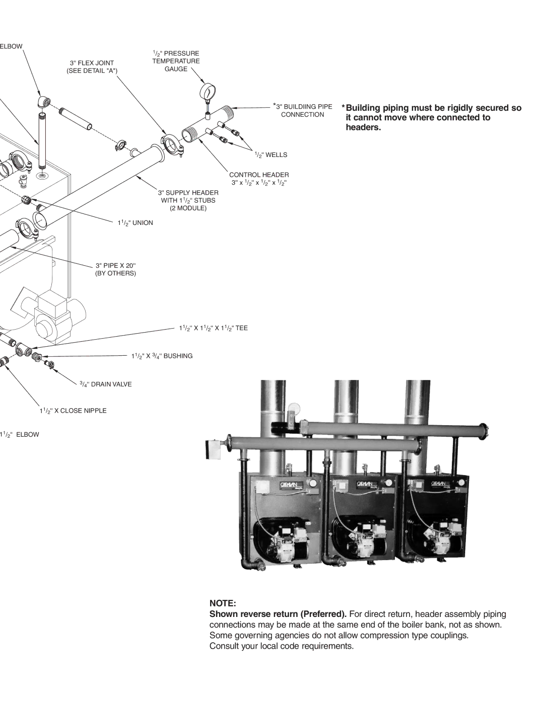
Finally, the L-Series is compatible with various boiler systems, allowing for seamless integration into existing hydronic heating systems. This flexibility, combined with the thoughtful design and advanced technology, makes Slant/Fin’s L-Series an excellent choice for those seeking an efficient, stylish, and reliable heating solution for their spaces. With the growing emphasis on energy efficiency and environmental sustainability, choosing the L-Series can lead to significant long-term savings while maintaining optimal comfort levels.

