Names and Functions of Individual Parts
Internal Circuit and Wiring
Other Functions
D-F8N / F8P / F8B
Vinyl sheath cable
| Brown |
| |
Switch | Load |
| |
main | Power | ||
| |||
circuit | Black | ||
|
| Brown |
|
Switch |
|
|
main | Black | Power |
circuit |
| |
Load suppy | ||
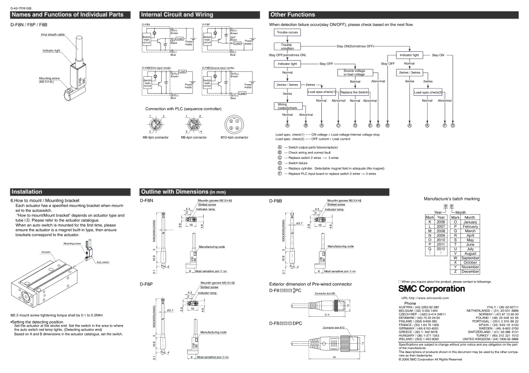
When detection failure occur(stay ON/OFF), please check based on the next flow.
Trouble occurs
Indicator light
Mounting screw | - | SMC |
(M2.5 4L) | F8B | |
| D |
|
suppy |
Blue
| Load | |
| Brown | |
Switch |
| |
main | Power | |
circuit | ||
suppy | ||
| ||
| Blue |
Blue |
| Brown | |
Switch |
| |
main | Power | |
circuit | ||
suppy | ||
| ||
| Load | |
| Blue |
| Trouble |
|
|
|
|
|
|
| Stay ON(Sometimes OFF) | ||||||||||||
| condition |
|
|
|
|
|
|
| |||||||||||||
|
|
|
|
|
|
|
|
|
|
|
|
|
|
|
|
|
|
|
| ||
|
|
|
|
|
|
|
|
|
|
|
|
|
|
|
|
|
|
|
|
|
|
Stay OFF(sometimes ON) |
|
|
|
|
|
|
| ||||||||||||||
|
|
|
|
|
|
| |||||||||||||||
|
|
|
|
|
|
|
|
|
|
|
|
|
|
|
|
|
|
|
|
| |
|
|
|
|
|
|
|
|
|
|
|
|
|
|
|
|
|
|
| Stay |
| OFF |
| Indicator light |
|
|
|
|
| Stay OFF |
|
|
|
|
| |||||||||
|
|
|
|
|
|
|
|
|
|
| |||||||||||
|
|
|
|
|
| ||||||||||||||||
|
|
|
|
|
|
|
|
|
|
|
|
|
|
|
|
|
|
|
|
| |
|
|
|
|
|
|
|
|
|
|
|
|
|
|
|
|
|
|
|
|
| |
|
|
|
|
|
|
|
|
|
|
|
|
| Source voltage |
|
|
|
| ||||
| Normal | ||||||||||||||||||||
|
|
|
|
|
|
|
|
|
|
| or load voltage |
|
|
|
| ||||||
|
|
|
|
|
|
|
|
|
|
|
|
|
|
|
|
| |||||
|
|
|
|
|
|
|
|
|
|
|
|
|
|
|
|
|
|
|
| ||
|
|
|
|
|
|
|
|
|
|
|
|
| Normal |
|
| Abnormal | |||||
| 2wires / 3wires | 2wires | |||||||||||||||||||
|
|
|
|
|
|
|
|
|
|
|
|
|
|
|
|
|
| ||||
|
|
|
|
|
|
|
|
|
|
|
|
|
|
|
|
|
|
|
|
| |
|
|
|
|
|
| Load spec.check(1) |
|
|
| Replace the Switch |
|
|
|
|
| ||||||
| 3wires |
|
|
|
|
|
|
|
|
|
|
| |||||||||
|
|
|
|
|
|
|
|
|
|
|
|
|
|
|
|
|
|
|
| ||
|
|
|
|
|
|
|
|
|
|
|
|
|
|
|
|
|
|
|
|
| |
|
|
|
|
|
| Normal Abnormal Normal | Abnormal | ||||||||||||||
| Wiring |
|
|
|
|
|
|
|
|
|
|
|
|
|
|
|
|
|
|
| |
Indicator light |
| Stay ON |
| ||
|
|
|
Normal
2wires / 3wires
3wires 2wires
Load spec.check(2)![]()
Normal Abnormal
Connection with PLC (sequence controller)
1 | 4 | 1 | 2 |
|
|
|
|
|
| 2 | 1 |
|
|
|
| 3 | 4 |
3 |
| 3 | 4 |
|
|
(output)check |
|
Normal | Abnormal |
A | B | A | C | D | E B | B | A | A | F D |
Load spec. check(1) | ON voltage > Load |
|
|
|
| ||||
Load spec. check(2) | OFF current > Leak current |
|
|
|
|
|
| ||
A
B
C
D
E
F
Installation
Outline with Dimensions (in mm)
6.How to mount / Mounting bracket
Mountin gscrew M2.5![]() 4
4![]()
| Mountin gscrew M2.5 4 |
|
Manufacture’s batch marking
Each actuator has a specified mounting bracket when mount- ed to the autoswitch.
“How to mount/Mount bracket” depends on actuator type and tube I.D. Please refer to the actuator catalogue.
When an auto switch is mounted for the first time, please ensure the actuator is a magnet
Mounting screw
Actuator
Auto switch
500(3000)(5000) | 2.8 |
3 |
|
10.9 |
|
| 4 |
3.1 |
|
Slotted screw
4.3Indicator lamp
2
10 | 4.6 |
|
Manufacturing code
SMC
D-F8N
8Most sensitive position
|
|
|
|
| Slotted screw |
|
|
| 4.3 |
| Indicator lamp |
|
|
| 2 |
|
|
500(3000)(5000) | 2.7 | 2.8 | 10 | 4.6 | |
| |||||
|
|
| |||
|
|
|
|
| Manufacturing code |
3 |
|
|
|
|
|
10.9 |
|
|
|
| |
| 4 |
|
|
|
|
3.1 |
|
| 8 | Most sensitive position | |
|
|
|
|
| |
Year ![]()
Mark Year
K2006
L2007 M 2008
N2009
O2010
P2011
Q2012
![]() Month
Month
Mark | Month |
O | January |
P | February |
Q | March |
R | April |
S | May |
T | June |
U | July |
V | August |
W | September |
X | October |
Y | November |
Z | December |
M2.5 mount screw tightening torque shall be 0.1 to 0.2N•m
•Setting the detecting position
Set the actuator at the stroke end. Set the switch in the area to where the auto switch red lamp lights. (Detecting actuator end)
Based on A and B dimensions in the actuator catalogue, set the switch.
D-F8P
500(3000)(5000) | 2.7 | 2.8 |
|
| |
3 |
|
|
10.9 |
|
|
| 4 |
|
3.1 |
|
|
Mountin gscrew M2.5![]() 4
4![]()
Slotted screw
4.3Indicator lamp
2
10 | 4.6 |
|
Manufacturing code
SMC
8 Most sensitive position
Exterior dimension of | ||||||||
|
|
|
|
| BAPC | |||
|
|
| ||||||
|
|
|
|
|
|
| Connector size M8 |
|
10 |
31.4 |
D-F8 

 DPC
DPC
Connector size M12
14 |
44 |
When you inquire about the product, please contact to followings.
URL http://www.smcworld.com
Phone
AUSTRIA / (43) | ITALY / (39) |
BELGIUM / (32) | NETHERLANDS / (31) |
CZECH REP. / (420) | NORWAY / (47) 67 12 90 20 |
DENMARK / (45) 70 25 29 00 | POLAND / (48) |
FINLAND / (358) | PORTUGAL / (351) 2 610 89 22 |
FRANCE / (33) | SPAIN / (34) |
GERMANY / (49) 6103 4020 | SWEDEN / (46) |
GREECE / (30) 1- 342 6076 | SWITZERLAND / (41) |
HUNGARY / (36) | TURKEY / (90) 212 221 1512 |
IRELAND / (353) | UNITED KINGDOM / (44) |
Specifications are subject to change without prior notice and any obligation on the part of the manufacturer.
The descriptions of products shown in this document may be used by the other compa- nies as their trademarks.
© 2006 SMC Corporation All Rights Reserved