V) MAINTENANCE

Do not attempt to repair your water heater. Call a qualified Oil-Burner Technician for service. Turn “OFF” the electric power whenever the water supply is shut off. Before calling for service, check that:

1.The heater is properly filled.

2.The electrical supply has not been interrupted.

Professional Maintenance

Except for external appearance and area tidiness, the fol- lowing steps should be performed only by a qualified Oil- Burner Technician.

1.Lift out the flue baffle to clean the flue. (On rear and combination flue heaters, the top cover, insulation and flue top cover must be removed.)

2.Insert a flue brush down the flue passage way(s) to remove soot and dirt. Soot or carbon that falls into the combustion chamber will burn up within a very short time.

3.In normal use, there should be no large accumulation of soot in the combustion chamber. If there is, remove the burner and carefully brush or vacuum the combustion chamber.

Flue Pipes

Once a year, inspect the flue pipe leading from the heater to the chimney. If corrosion is evident, or discolouration at the joints can be seen, replace the flue pipes. This should be done by a qualified Oil-Burner Technician. Flue pipes must be replaced by the same size flue pipe as the flue collar (breech connection) at the heater.

Keep the air ventilation openings unobstructed. If dust and lint is seen accumulating around the openings, remove it.

Do not pile cartons, papers, or combustible materials on top, or near the heater (see Figure 1).

Draining and Flushing

It is recommended that the tank be drained and flushed every 6 months to remove sediment that may build up dur- ing operation. The water heater should be drained if being shut down during freezing temperatures. To drain the tank, perform the following steps:

1.Turn off the electrical supply to the water heater.

2.Close the cold water inlet valve.

3.Open a nearby hot water faucet.

4.Connect a hose to the drain valve and terminate it to an adequate drain.

Note: The drain hose should be rated for at least 93°C (200°F). If the drain hose does not have this rating, open the cold water inlet valve and a nearby hot faucet until the water is no longer hot.

5.Open the water heater drain valve and allow all the water to drain from the tank. Flush the tank with water as needed to remove sediment.

6.Close the drain valve, refill the tank, and restart the heater as directed under “Water Heater Operation”.

If the water heater is going to be shut down for an extended period, the drain valve should be left open.

Important: Condensation may occur when refilling the tank and should not be confused with a tank leak.

Temperature and Pressure Relief Valve

Combustion Tests

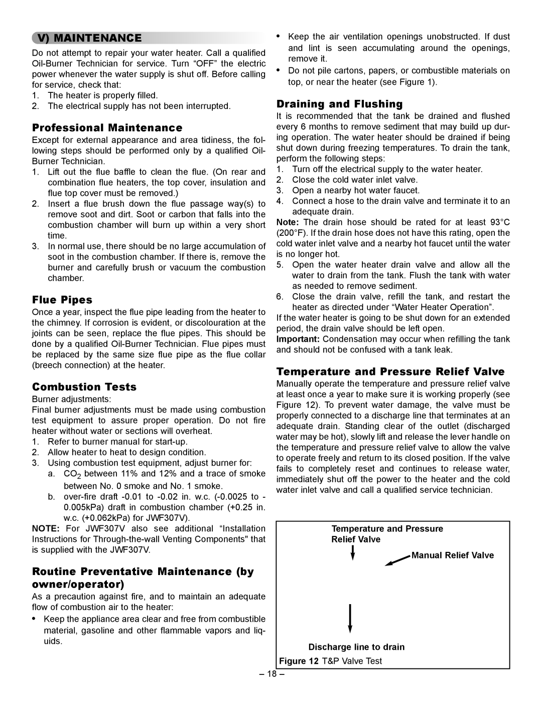
Manually operate the temperature and pressure relief valve

Burner adjustments:

at least once a year to make sure it is working properly (see

Figure 12). To prevent water damage, the valve must be

Final burner adjustments must be made using combustion

properly connected to a discharge line that terminates at an

test equipment to assure proper operation. Do not fire

adequate drain. Standing clear of the outlet (discharged

heater without water or sections will overheat.

water may be hot), slowly lift and release the lever handle on

1. Refer to burner manual for start-up.

the temperature and pressure relief valve to allow the valve

2. Allow heater to heat to design condition.

to operate freely and return to its closed position. If the valve

3. Using combustion test equipment, adjust burner for:

fails to completely reset and continues to release water,

a. CO2 between 11% and 12% and a trace of smoke

immediately shut off the power to the heater and the cold

between No. 0 smoke and No. 1 smoke.

water inlet valve and call a qualified service technician.

b. over-fire draft -0.01 to -0.02 in. w.c. (-0.0025 to -


0.005kPa) draft in combustion chamber (+0.25 in.


w.c. (+0.062kPa) for JWF307V).


NOTE: For JWF307V also see additional “Installation


Temperature and Pressure

Instructions for Through-the-wall Venting Components" that


Relief Valve


is supplied with the JWF307V.


Manual Relief Valve


Routine Preventative Maintenance (by


owner/operator)


As a precaution against fire, and to maintain an adequate


flow of combustion air to the heater:


Keep the appliance area clear and free from combustible


material, gasoline and other flammable vapors and liq-

uids.


Discharge line to drain


Figure 12 T&P Valve Test


– 18

Page 18
Image 18
Smith Cast Iron Boilers JW517, JWF507, JW727, JWF657, JW527, JW327, JW317, JWF307V, JW717 manual Maintenance

JW327, JW517, JWF307V, JWF657, JWF507 specifications

Smith Cast Iron Boilers have established a strong reputation in the heating industry for their durable, efficient, and reliable products. Among their notable models are the JWF507, JW717, JWF657, JW327, and JW517. Each of these models incorporates advanced technologies and unique features tailored to meet various heating demands.

The JWF507 is renowned for its exceptional thermal efficiency. This boiler utilizes a water-to-water heat exchanger, providing efficient heat transfer, which significantly reduces fuel consumption. Its robust cast iron construction ensures longevity, even in harsh conditions, while an oversized heat exchanger design enhances performance and reliability.

The JW717 model stands out with its ability to handle large-scale heating needs. This boiler features a multi-pass design that maximizes heat transfer and minimizes the chance of overheating. Additionally, it is equipped with an advanced control system that allows for precise temperature adjustments, ensuring optimal comfort in residential and commercial settings.

The JWF657 introduces a unique burner design, which improves combustion efficiency and reduces emissions. This model also features a built-in pump which enhances the system's circulation, helping to maintain consistent and comfortable heating throughout the space. With its energy-efficient attributes, the JWF657 is a top choice for environmentally-conscious consumers.

Next in line, the JW327 model is designed for versatility and adaptability. This boiler can easily be integrated into various heating systems, making it suitable for both retrofit and new construction projects. Its compact size allows for easy installation in tight spaces, while its high-efficiency rating contributes to lower energy bills.

Lastly, the JW517 model is known for its reliability and user-friendly design. This boiler is equipped with an intuitive control panel, making operation simple and straightforward. Its rugged cast iron construction is designed to withstand rigorous use, providing peace of mind for users who seek a dependable heating solution.

In summary, Smith Cast Iron Boilers offer a diverse portfolio with models like the JWF507, JW717, JWF657, JW327, and JW517, each boasting unique features and technologies. From high thermal efficiency and advanced combustion systems to user-friendly designs and rugged durability, these boilers are crafted to deliver optimal performance in various heating applications. Whether for residential or commercial use, these models exemplify the superior quality and innovation that Smith Cast Iron Boilers is known for.