Tube and Latch Kit | Installation Instructions |
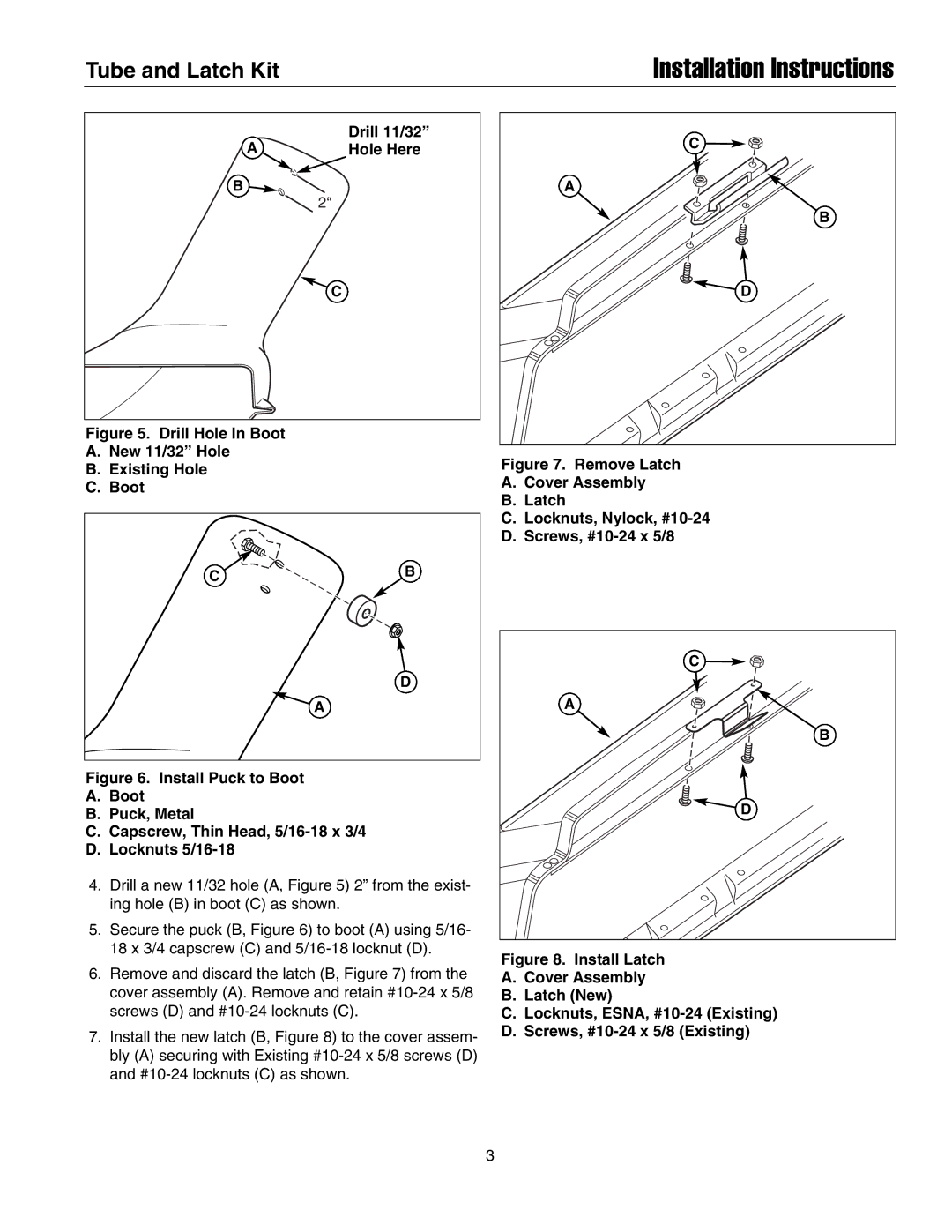
Drill 11/32”
AHole Here
B
2“
C
Figure 5. Drill Hole In Boot
A.New 11/32” Hole
B.Existing Hole
C.Boot
CB
D
A
Figure 6. Install Puck to Boot
A.Boot
B.Puck, Metal
C.Capscrew, Thin Head, 5/16-18 x 3/4
D.Locknuts 5/16-18
4.Drill a new 11/32 hole (A, Figure 5) 2” from the exist- ing hole (B) in boot (C) as shown.
5.Secure the puck (B, Figure 6) to boot (A) using 5/16- 18 x 3/4 capscrew (C) and
6.Remove and discard the latch (B, Figure 7) from the cover assembly (A). Remove and retain
7.Install the new latch (B, Figure 8) to the cover assem- bly (A) securing with Existing
C |
A |
B |
D |
Figure 7. Remove Latch
A.Cover Assembly
B.Latch
C.Locknuts, Nylock, #10-24
D.Screws, #10-24 x 5/8
C |
A |
B |
D |
Figure 8. Install Latch
A.Cover Assembly
B.Latch (New)
C.Locknuts, ESNA, #10-24 (Existing)
D.Screws, #10-24 x 5/8 (Existing)
3