NOTE
Not all hardware supplied with horn kit will be used for this installation. Discard excess hardware. Refer to figure 1 to familiarize yourself with the assembly.
NOTE
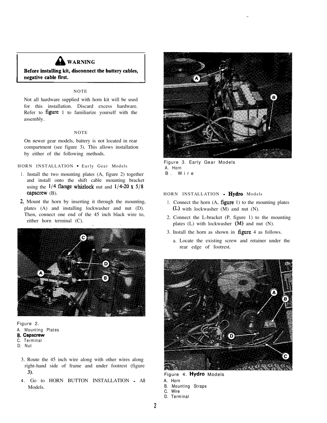
On newer gear models, battery is not located in rear compartment (see figure 3). This allows installation by either of the following methods.
HORN INSTALLATION - Early Gear Models
1 . Install the two mounting plates (A, figure 2) together and install onto the shift cable mounting bracket using the l/4 flange whizlock nut and
2., Mount the horn by inserting it through the mounting, plates (A) and installing lockwasher and nut (D). Then, connect one end of the 45 inch black wire to,
either horn terminal (C).
Figure 2.
A. Mounting Plates
6.capscrew C. Terminal D. Nut
3.Route the 45 inch wire along with other wires along
3).
4.Go to HORN BUTTON INSTALLATION - All Models.
Figure 3. Early Gear Models
A. Horn
B . W i r e
HORN INSTALLATION - Hydra Models
1 . Connect the horn (A, figure 1) to the mounting plates
(L)with lockwasher (M) and nut (N).
2.Connect the
3.Install the horn as shown in figure 4 as follows.
a. Locate the existing screw and retainer under the rear edge of footrest.
Figure 4. Hydra Models
A.Horn
B.Mounting Straps
C.Wire
D.Terminal
2