b. Remove this existing screw, and install new 5/ 16- 18 x 1 screw (F), being sure the retainer is in original position.
c. Place the horn assembly into position onto the screw and install the flange whizlock nut(E). The horn should appear as in figure 4.
4.,Connect the
5.Go to HORN BUTTON INSTALLATION - All Models.
HORN BUTTON INSTALLATION - All Models
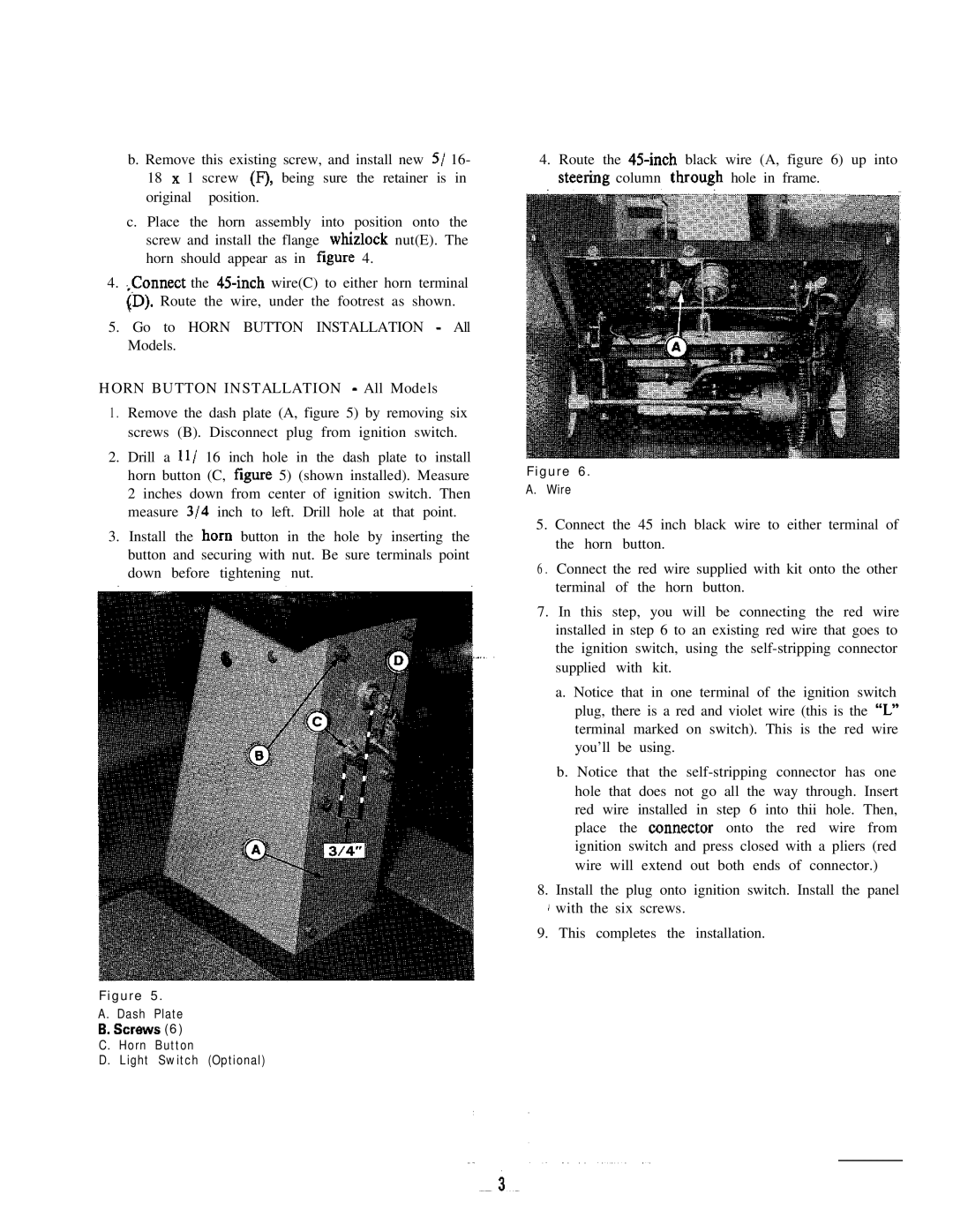
1 . Remove the dash plate (A, figure 5) by removing six screws (B). Disconnect plug from ignition switch.
2.Drill a Il/ 16 inch hole in the dash plate to install horn button (C, figure 5) (shown installed). Measure 2 inches down from center of ignition switch. Then measure 314 inch to left. Drill hole at that point.
3.Install the horn button in the hole by inserting the button and securing with nut. Be sure terminals point down before tightening nut.
Figure 5.
A. Dash Plate
6.screws (6) C. Horn Button
D. Light Switch (Optional)
4.Route the
Figure 6.
A.Wire
5.Connect the 45 inch black wire to either terminal of the horn button.
6 . Connect the red wire supplied with kit onto the other terminal of the horn button.
7.In this step, you will be connecting the red wire installed in step 6 to an existing red wire that goes to the ignition switch, using the
a. Notice that in one terminal of the ignition switch plug, there is a red and violet wire (this is the “L” terminal marked on switch). This is the red wire you’ll be using.
b. Notice that the
8.Install the plug onto ignition switch. Install the panel ![]() ’ with the six screws.
’ with the six screws.
9.This completes the installation.