Section 2 - OPERATING INSTRUCTIONS
2.3 STARTING & OPERATION
2.3.1. ENGINE (ELECTRIC START)
IMPORTANT: When the ignition key is turned to “START”, the engine will turn over, but willnot start unless the Clutch/Brake pedal is pressed all the way down, the Blade Lever is in the “Off” position (See Figure 2.5). The operator should be in the seat. Start engine as follows:
1.Move transmission shift lever to (N) Neutral position. DO NOT start engine with transmission shift lever in a drive position.
WARNING
It is possible to start engine with transmission shift lever in a drive position. Follow starting instructions carefully.
2.Make certain the Blade Lever is in the “Off” position. See Figure 2.4.
BLADE LEVER IN “OFF” POSITION
RELEASE BLADE
PEDALS
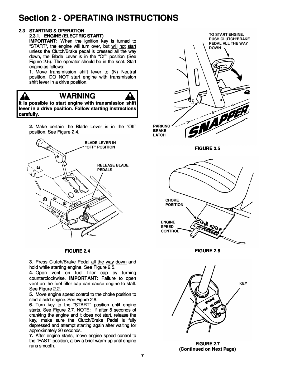
TO START ENGINE,
PUSH CLUTCH/BRAKE
PEDAL ALL THE WAY
DOWN
PARKING
BRAKE
LATCH
FIGURE 2.5
CHOKE
POSITION
ENGINE
SPEED
CONTROL
FIGURE 2.4
3.Press Clutch/Brake Pedal all the way down and hold while starting engine. See Figure 2.5.
4.Open vent on fuel filler cap by turning counterclockwise. IMPORTANT: Failure to open vent on the fuel filler cap can cause engine to stall. See Figure 2.2.
5.Move engine speed control to the choke position to start a cold engine. See Figure 2.6.
6.Turn key to the “START” position until engine starts. See Figure 2.7. NOTE: If after 5 seconds of cranking the engine and it does not start, release the key, make sure the Clutch/Brake Pedal is fully depressed and attempt starting again after waiting for approximately 20 seconds.
7.After engine starts, move engine speed control to the “FAST” position, allow a brief
FIGURE 2.6
KEY
FIGURE 2.7
(Continued on Next Page)
7