Section 2 - OPERATING INSTRUCTIONS
WARNING
DO NOT leave machine with the engine running. Stop engine. Stop blade. Shift to neutral. Engage parking brake. Remove key.
2.4STOPPING - ENGINE, WHEEL DRIVE, BLADE 2.4.1. ENGINE
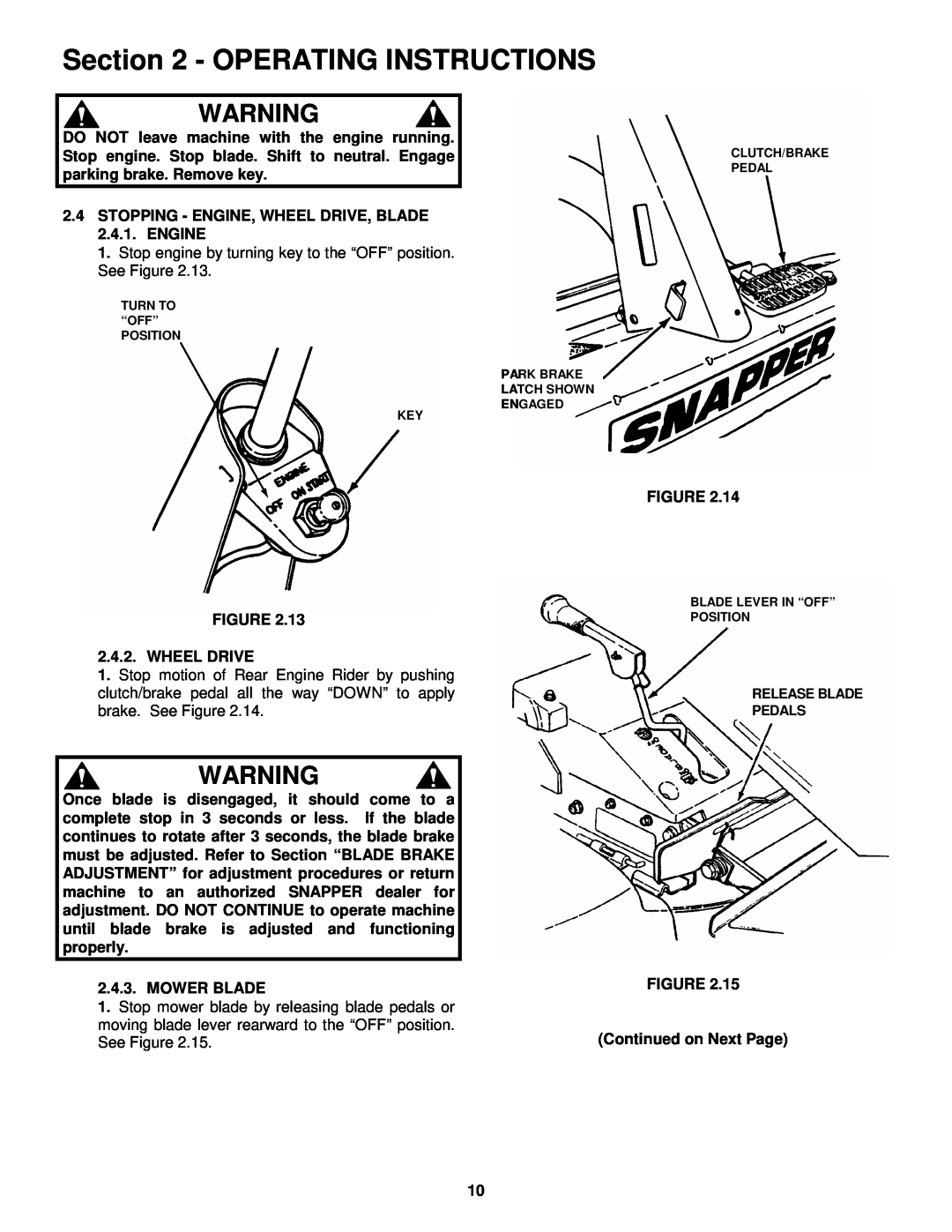
1.Stop engine by turning key to the “OFF” position. See Figure 2.13.
TURN TO “OFF”
POSITION
PARK BRAKE
LATCH SHOWN
ENGAGED
KEY
CLUTCH/BRAKE PEDAL
FIGURE 2.13
2.4.2. WHEEL DRIVE
1.Stop motion of Rear Engine Rider by pushing clutch/brake pedal all the way “DOWN” to apply brake. See Figure 2.14.
WARNING
Once blade is disengaged, it should come to a complete stop in 3 seconds or less. If the blade continues to rotate after 3 seconds, the blade brake must be adjusted. Refer to Section “BLADE BRAKE ADJUSTMENT” for adjustment procedures or return machine to an authorized SNAPPER dealer for adjustment. DO NOT CONTINUE to operate machine until blade brake is adjusted and functioning properly.
2.4.3. MOWER BLADE
1.Stop mower blade by releasing blade pedals or moving blade lever rearward to the “OFF” position. See Figure 2.15.
FIGURE 2.14
BLADE LEVER IN “OFF”
POSITION
RELEASE BLADE
PEDALS
FIGURE 2.15
(Continued on Next Page)
10