Section 1 - FAMILIARIZATION
IMPORTANT: The figures and illustrations in this manual are provided for reference only and may differ from your specific model. Contact your Snapper dealer if you have questions.
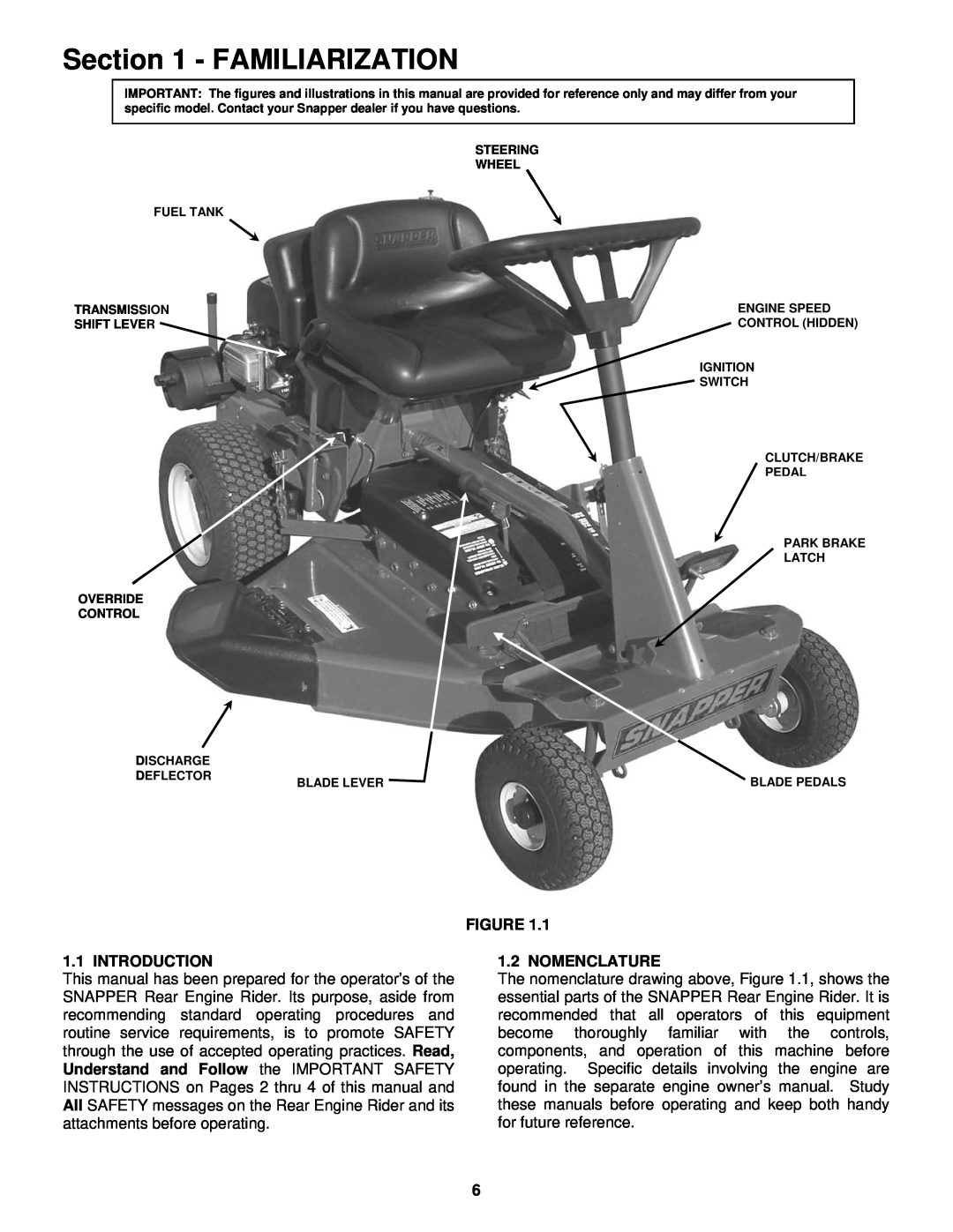
STEERING
WHEEL
FUEL TANK
TRANSMISSION | ENGINE SPEED |
SHIFT LEVER | CONTROL (HIDDEN) |
IGNITION
![]() SWITCH
SWITCH
CLUTCH/BRAKE
PEDAL
PARK BRAKE
LATCH
OVERRIDE
CONTROL
DISCHARGE |
|
|
DEFLECTOR | BLADE LEVER | BLADE PEDALS |
|
FIGURE 1.1
1.1 INTRODUCTION
This manual has been prepared for the operator’s of the SNAPPER Rear Engine Rider. Its purpose, aside from recommending standard operating procedures and routine service requirements, is to promote SAFETY through the use of accepted operating practices. Read, Understand and Follow the IMPORTANT SAFETY INSTRUCTIONS on Pages 2 thru 4 of this manual and All SAFETY messages on the Rear Engine Rider and its attachments before operating.
1.2 NOMENCLATURE
The nomenclature drawing above, Figure 1.1, shows the essential parts of the SNAPPER Rear Engine Rider. It is recommended that all operators of this equipment become thoroughly familiar with the controls, components, and operation of this machine before operating. Specific details involving the engine are found in the separate engine owner’s manual. Study these manuals before operating and keep both handy for future reference.
6