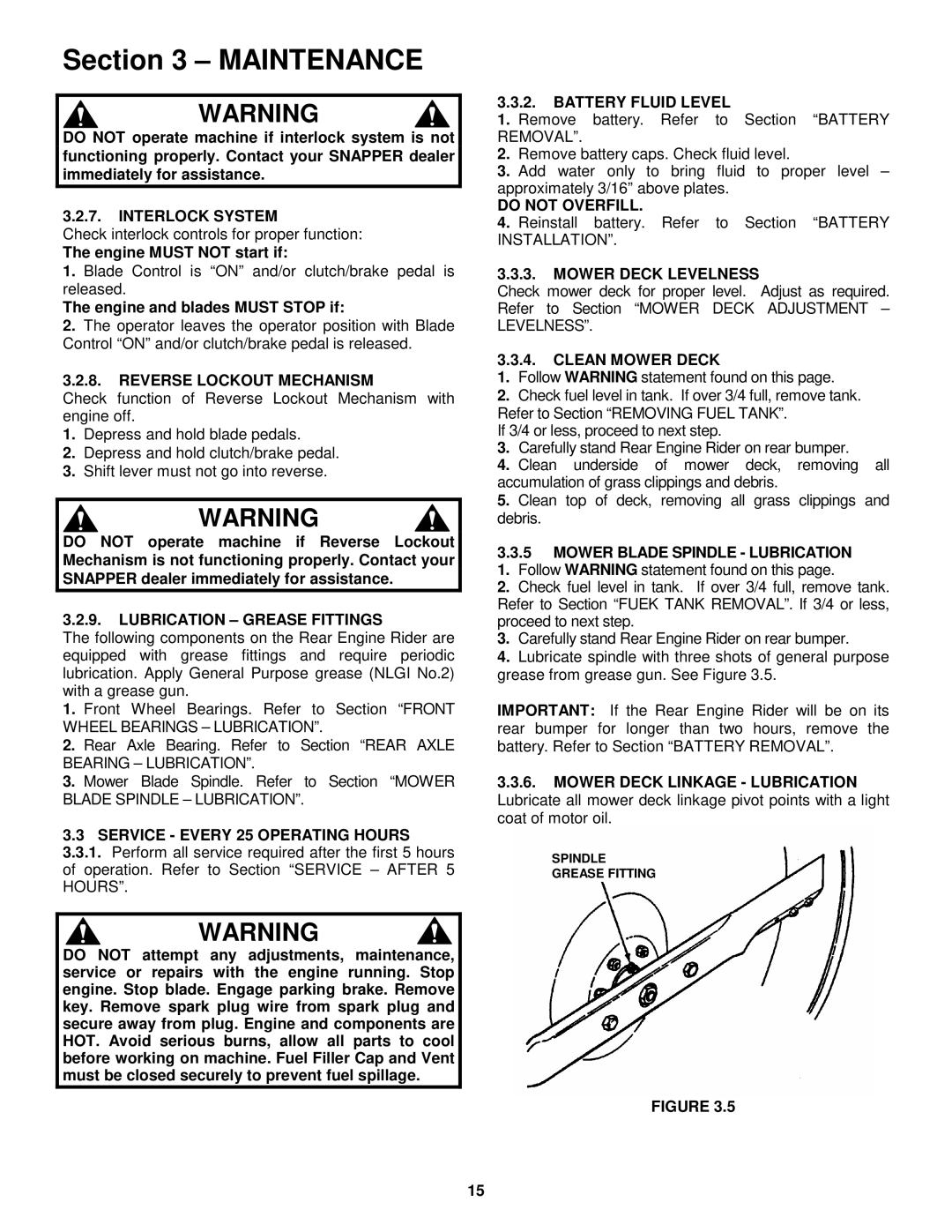
301222BE, 281222BE, 3314522BVE, 331522KVE specifications
Snapper 301222BE, 3314522BVE, 281222BE, and 331522KVE are advanced lawn care equipment offerings that cater to both residential and commercial users, emphasizing efficiency, durability, and innovative technology. Each model showcases unique features designed to optimize performance and enhance user experience.The Snapper 301222BE model is known for its robust build, equipped with a powerful Briggs & Stratton engine that ensures reliable starting and sustained performance. Its Easy Start technology simplifies the ignition process, making it user-friendly even for novice operators. The 21-inch steel cutting deck provides a balanced mowing experience, ensuring even grass cutting with minimal effort. This model also features a dual (Rear and Side) discharge function, giving users flexibility in managing grass clippings.
Similarly, the Snapper 3314522BVE combines a powerful engine with a reinforced steel deck, ensuring durability and longevity. What sets it apart is its cutting-edge Smart Mulching technology, which finely chops grass clippings and redistributes them back into the lawn as natural fertilizer. This not only enhances lawn health but also reduces the need for additional lawn care products. The 3314522BVE also incorporates a user-friendly height adjustment lever, allowing operators to easily switch between cutting heights.
The Snapper 281222BE is designed with an emphasis on compactness without sacrificing power. It features a 19-inch cutting deck and a lightweight design, making it perfect for maneuvering around smaller lawns and tight spaces. The 281222BE also boasts an ergonomic handle for increased comfort during prolonged use, making it a perfect choice for homeowners seeking a practical and effective mowing solution.
On the other hand, the 331522KVE stands out with its innovative technology featuring a variable speed self-propulsion system, allowing users greater control over their mowing speed. This model also includes an integrated grass catcher which efficiently collects clippings, reducing cleanup time after mowing. The high-wheel design on this model enhances stability on uneven terrain, making it suitable for a wide range of lawn conditions.
In summary, Snapper’s range of models, including the 301222BE, 3314522BVE, 281222BE, and 331522KVE, exemplifies a blend of innovative engineering and practical design. With features tailored to meet diverse lawn care needs, these models represent a step forward in enhancing efficiency and ease of use in lawn maintenance. Whether for residential lawns or commercial landscapes, Snapper mowers are designed to deliver exceptional results while ensuring user comfort and satisfaction.

