DEALER
26" HIGH WHEEL MOWERS
This SNAPPER High Wheel Mower is equipped with a Blade Brake Clutch (BBC). This allows the machine to be started and operated with the blade disengaged (OFF). Releasing the blade control on this machine STOPS only the blade. The engine continues to run. The engine is stopped by moving the engine speed control to STOP position. These mowers are designed for quick
STEP 1: Remove High Wheel mower from crate.
STEP 2: Rotate handle brackets until they line up with holes in rear case. Install bolts (5/16"X 1" carriage) from inside and use
STEP 3: Assemble handles onto handle brackets using hardware provided in kit. Tighten to 12 to 22 ft. lbs. NOTE: Make sure control cables are routed on the inside of handles and are not pinched.
STEP 4: Install speed control rod into speed control sector. See Figure 1.
Speed Control
Selector
Speed
Control
Rod
FIGURE 1
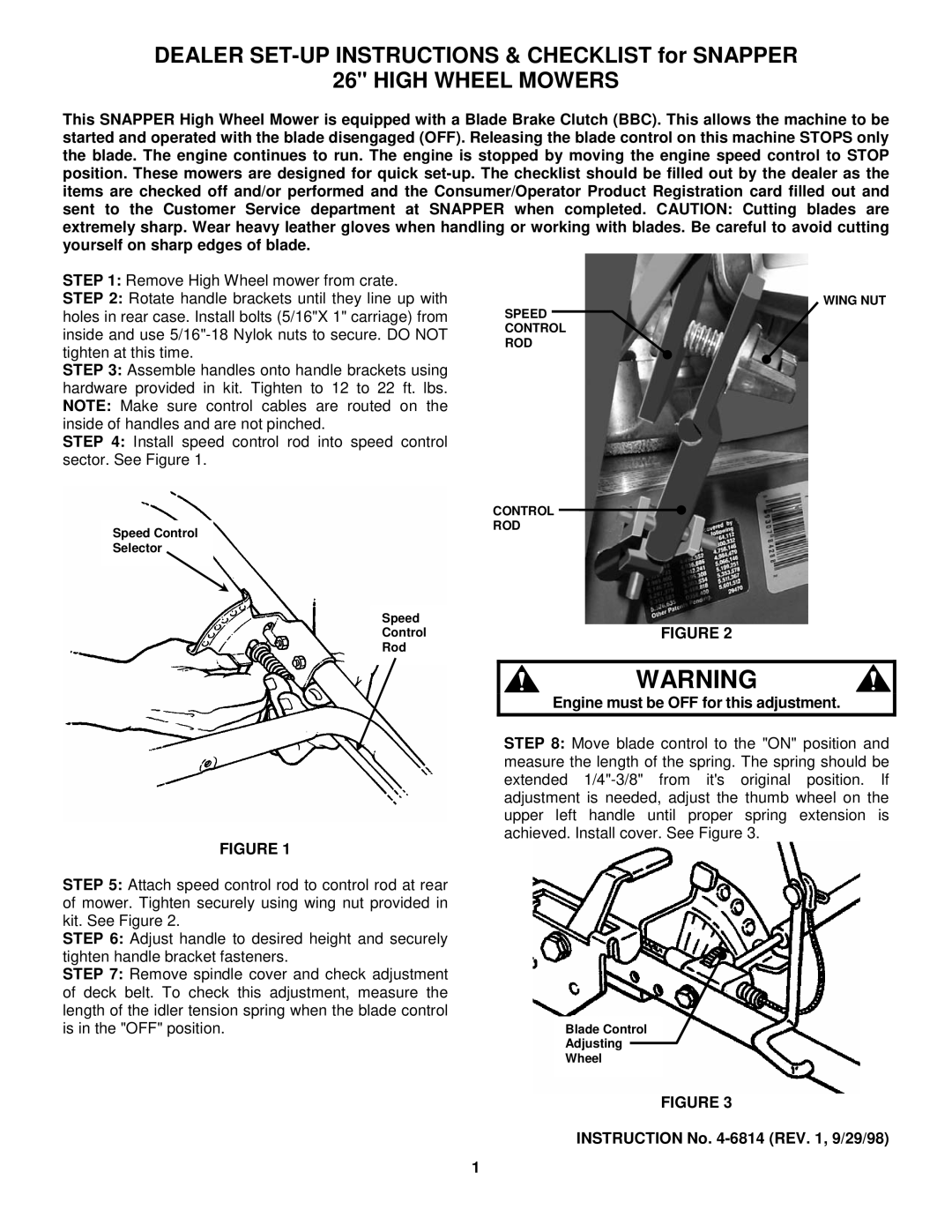
STEP 5: Attach speed control rod to control rod at rear of mower. Tighten securely using wing nut provided in kit. See Figure 2.
STEP 6: Adjust handle to desired height and securely tighten handle bracket fasteners.
STEP 7: Remove spindle cover and check adjustment of deck belt. To check this adjustment, measure the length of the idler tension spring when the blade control is in the "OFF" position.
WING NUT
SPEED CONTROL ROD
CONTROL
ROD
FIGURE 2
WARNING
Engine must be OFF for this adjustment.
STEP 8: Move blade control to the "ON" position and measure the length of the spring. The spring should be extended
Blade Control
Adjusting
Wheel
FIGURE 3
INSTRUCTION No. 4-6814 (REV. 1, 9/29/98)
1