Manuals
/
Snapper
/
Lawn and Garden
/
Lawn Mower
Snapper
C216012RV, GP215512KWV Repair & Adjustments, Figure, Replacing Driven Disc Rubber Ring
Models:
GP216512RV
GP215512KWV
C216012RV
1
15
28
28
Download
28 pages
50.15 Kb
12
13
14
15
16
17
18
19
Troubleshooting
Warranty
Maintenance
2.5CUTTING HEIGHT ADJUSTMENT
Safety
Service - Annually
Page 15
Image 15
Page 14
Page 16
Page 15
Image 15
Page 14
Page 16
Contents
PUSH
Safety Instructions & Operator’s Manual for
21” STEEL DECK
WALK MOWERS COMMERCIAL MODEL SERIES
PREPARATION
IMPORTANT SAFETY INSTRUCTIONS
PROTECTION FOR CHILDREN
SLOPE OPERATION
OPERATION
MAINTENANCE AND STORAGE
TABLE OF CONTENTS
1.2 NOMENCLATURE
Section 1 - FAMILIARIZATION
FIGURE
1.1 INTRODUCTION
Section 2 - OPERATING INSTRUCTIONS
2.1PRE-STARTCHECK LIST
2.2STARTING & OPERATION 2.2.1. ENGINE & BLADE
2.5CUTTING HEIGHT ADJUSTMENT
2.4 HANDLE HEIGHT ADJUSTMENT
2.3 STOPPING
2.6RECYCLING OPERATION - OPTIONAL ACCESSORY
KAWASAKI ENGINES
Section 3 - MAINTENANCE
3.1INTRODUCTION
ROBIN ENGINES
Section 3 – MAINTENANCE
3.3 SERVICE - ANNUALLY
Section 4 - REPAIR & ADJUSTMENTS
4.2WHEEL DRIVE CONTROL ADJUSTMENT
4.3DRIVEN DISC SERVICE
Continued on next page FIGURE
4.3.1. Cleaning Drive Disc & Driven Disc
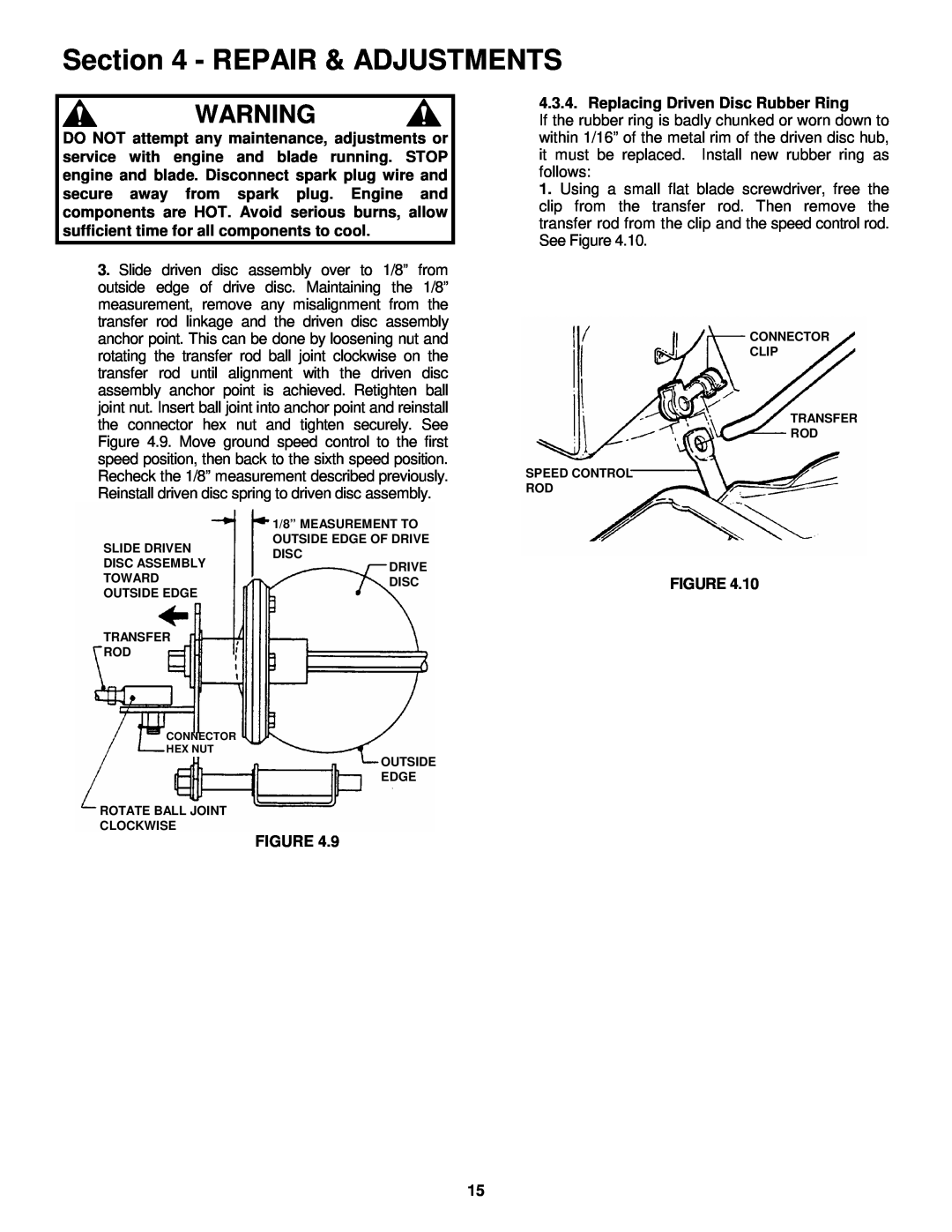
4.3.4. Replacing Driven Disc Rubber Ring
FIGURE
4.3.6. Replacement Of Bearing On Pulley End Of
FIGURE
CORRECTIVE ACTION
TROUBLESHOOTING
PROBLEM
PROBABLE CAUSE
MAINTENANCE PARTS
SERVICE SCHEDULE
3 YEAR LIMITED WARRANTY
PRIMARY MAINTENANCE
PRIMARY MAINTENANCE
PRIMARY MAINTENANCE
PRIMARY MAINTENANCE
SERVICE NOTES
SERVICE NOTES
Snapper products are built using engines that meet or exceed all applicable emissions requirements on the date manufactured. The labels on those engines contain very important emissions information and critical safety warnings. Read, Understand, and Follow all warnings and instructions in this manual, the engine manual, and on the machine, engine and attachments. If you have any questions about your Snapper product, contact your local authorized Snapper dealer or contact Snapper Customer Service at Snapper, McDonough, GA. 30253. Phone:
Top
Page
Image
Contents