Manuals
/
Snapper
/
Lawn and Garden
/
Lawn Mower
Snapper
ELP21702BV Operating Instructions, 2.2.ENGINE & BLADE, Choke Models Recoil Start, Figure
Models:
ELP21702BV
1
7
24
24
Download
24 pages
30.36 Kb
4
5
6
7
8
9
10
11
Troubleshooting
Air Filter Symbol P/N
Warranty
Maintenance
Battery Condition Chart
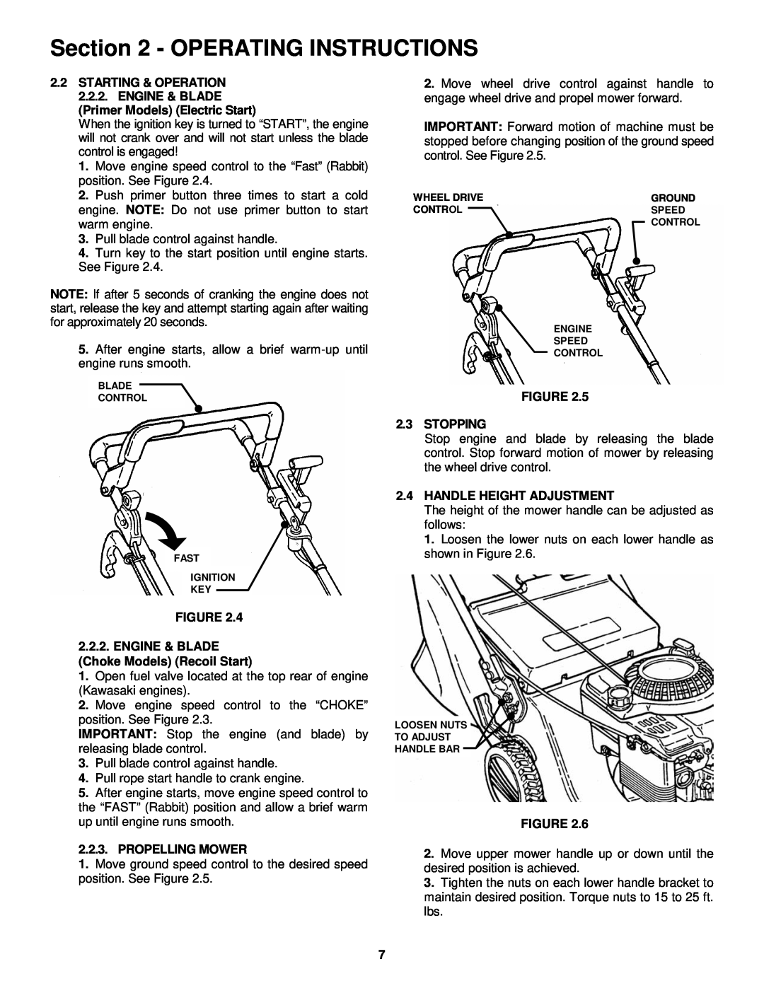
2.4HANDLE HEIGHT ADJUSTMENT
Safety
4.3BELT SERVICE
Page 7
Image 7
Page 6
Page 8
Page 7
Image 7
Page 6
Page 8
Contents
SELF-PROPELLED MODEL ELP21702BV
Safety Instructions & Operator’s Manual for
PREPARATION
IMPORTANT SAFETY INSTRUCTIONS
PROTECTION FOR CHILDREN
SLOPE OPERATION
OPERATION
MAINTENANCE AND STORAGE
TABLE OF CONTENTS
1.2 NOMENCLATURE
Section 1 - FAMILIARIZATION
FIGURE
1.1 INTRODUCTION
Primer Models Recoil Start
Section 2 - OPERATING INSTRUCTIONS
2.1PRE-STARTCHECK LIST
2.2STARTING & OPERATION 2.2.1. ENGINE & BLADE
2.2.3.PROPELLING MOWER
2.4HANDLE HEIGHT ADJUSTMENT
FIGURE 2.2.2.ENGINE & BLADE
Choke Models Recoil Start
2.5CUTTING HEIGHT ADJUSTMENT
3.2.3. WHEEL DRIVE CONTROL
Section 3 - MAINTENANCE
3.1INTRODUCTION
3.2.2. GREASE LEVEL IN TRANSMISSION
3.2.4. CHECK MOWER BLADE
Section 4 - REPAIR & ADJUSTMENTS
CUTTING EDGE OF
THUMBWHEEL ADJUSTER
DO NOTSHARPEN
BEYOND ORIGINAL
4.3BELT SERVICE
Section 4 - ADJUSTMENTS & REPAIR
Battery Condition Chart
Start Using
TROUBLESHOOTING
PROBLEM
Using Recoil Starter
MAINTENANCE/REPLACEMENT PARTS MAINTENANCE PARTS
MAINTENANCE SCHEDULE
1 WARNING INSTRUCTIONS
DECAL IDENTIFICATION
8HEIGHT CONTROL INSTRUCTION: Shows direction of movement of HEIGHT ADJUST HANDLE to select a change in height if cut from highest cutting height clockwise to the lowest height counter- clockwise. Note that there is a total of eleven heights of cut
CHUTE DEFLECTOR DECAL P/N
AIR FILTER SYMBOL P/N
DECAL P/N
2 YEAR LIMITED WARRANTY
NOTES
NOTES
SERIES
EUROPEAN 21” CAST ALUMINUM DECK WALK MOWERS
Top
Page
Image
Contents