Manuals
/
Snapper
/
Lawn and Garden
/
Lawn Mower
Snapper
EMRP216015B Adjustments & Repair, Continued from previous page
Models:
EMRP216015B
1
15
24
24
Download
24 pages
10.26 Kb
12
13
14
15
16
17
18
19
Troubleshooting
Warranty
Maintenance
2.4HANDLE HEIGHT ADJUSTMENT
Safety
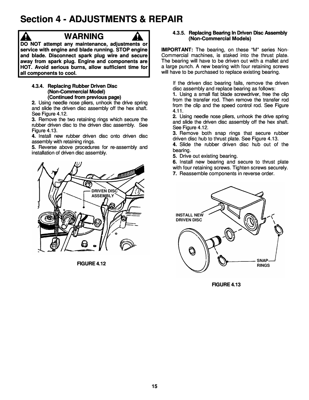
4.3DRIVEN DISC SERVICE
Page 15
Image 15
Page 14
Page 16
Page 15
Image 15
Page 14
Page 16
Contents
Safety Instructions & Operator’s Manual for
PROPELLED MODELS
EMRP216015B
PREPARATION
IMPORTANT SAFETY INSTRUCTIONS
PROTECTION FOR CHILDREN
SLOPE OPERATION
OPERATION
MAINTENANCE AND STORAGE
TABLE OF CONTENTS
Section 1 - FAMILIARIZATION
1.1 INTRODUCTION
1.2 NOMENCLATURE
Primer Models
Section 2 - OPERATING INSTRUCTIONS
2.1PRE-STARTCHECK LIST
2.2STARTING & OPERATION 2.2.1. ENGINE & BLADE
2.4HANDLE HEIGHT ADJUSTMENT
2.2.3.PROPELLING MOWER Self Propelled Models Only
FIGURE 2.3STOPPING
FIGURE FIGURE
2.5CUTTING HEIGHT ADJUSTMENT
2.7INSTALLATION of GRASS CATCHER
2.6 RECYCLING OPERATION
Section 3 - MAINTENANCE
3.2.2. CHECK GREASE LEVEL IN TRANSMISSION
Section 4 - ADJUSTMENTS & REPAIR
4.2WHEEL DRIVE CONTROL ADJUSTMENT
FIGURE 4.3.3. DRIVEN DISC ADJUSTMENT
4.3DRIVEN DISC SERVICE
4.3.1. Cleaning Drive Disc & Driven Disc
4.3.2. Drive Spring Repair/Replacement
FIGURE Continued on next page
FIGURE 4.3.4. Replacing Rubber Driven Disc Ring
Continued from previous page
Section 4 - ADJUSTMENTS & REPAIR
4.4.2.Transmission Poly-VBelt Replacement
Continued From Previous Page
PULLEY POSITION
CORRECTIVE ACTION
TROUBLESHOOTING
PROBLEM
PROBABLE CAUSE
MAINTENANCE PARTS
SERVICE SCHEDULE
DECAL IDENTIFICATION
EUROPEAN PERFORMANCE
3 YEAR LIMITED WARRANTY
Page
WALK BEHIND MOWERS “M” MODEL SERIES
EUROPEAN 21” STEEL DECK
Top
Page
Image
Contents