Troubleshooting, Adjustment, & Service
BLADE BRAKE ADJUSTMENT
![]() WARNING
WARNING
•DO NOT place hands or feet under mower deck and away from blade.
•This machine is capable of throwing objects and debris. Keep bystanders away.
•DO NOT touch any rotating parts (pulleys, belts, etc.). Loose clothing, gloves, etc. can become entangled.
The mower blade should stop within 5 seconds after the Blade Engagement Lever is moved to the DISEN- GAGED position. This adjustment is checked by:
1.Remove blade clutch cover plate (A, Figure 19).
2.Start engine.
3.With mower blade engagement lever in the DISEN- GAGED position, note spindle bolt (A, Figure 18) in center of pulley (bolt is fastened to blade spindle and indicates blade rotation). If clutch rod is adjusted properly, spindle should not turn.
Figure 18 - Blade Spindle Brake
A.Spindle Bolt
4.Move mower blade engagement lever into the ENGAGED position. Spindle should begin turning.
5.Disengage clutch. Blade should stop turning within 5 seconds. If the blade does not stop within 5 seconds, see Blade Clutch Adjustment Section.
Figure 19 - Belt Adjustments
A.Clutch Cover Plate
B.Mower Blade Idler Pulley Lock Nut
C.Mower Blade Idler Pulley Adjustment Nut
D.Traction Drive Idler Pulley Lock Nut
E.Traction Drive Idler Pulley Adjustment Nut
MOWER BELT ADJUSTMENT
If the mower blade drive belt needs adjustment:
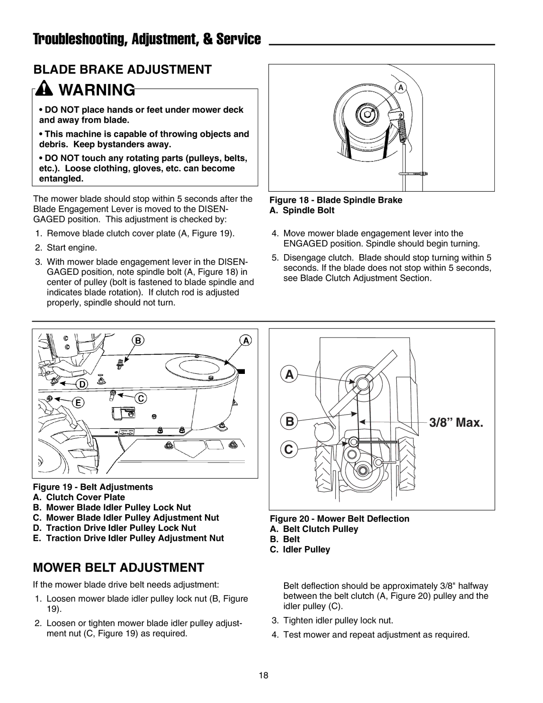
1.Loosen mower blade idler pulley lock nut (B, Figure 19).
2.Loosen or tighten mower blade idler pulley adjust- ment nut (C, Figure 19) as required.
A ![]()
B | 3/8” Max. |
C
Figure 20 - Mower Belt Deflection
A.Belt Clutch Pulley
B.Belt
C.Idler Pulley
Belt deflection should be approximately 3/8" halfway between the belt clutch (A, Figure 20) pulley and the idler pulley (C).
3.Tighten idler pulley lock nut.
4.Test mower and repeat adjustment as required.
18
