SECTION 2 - SET-UP INSTRUCTIONS FOR SNAPPER 73” FINISHING MOWER
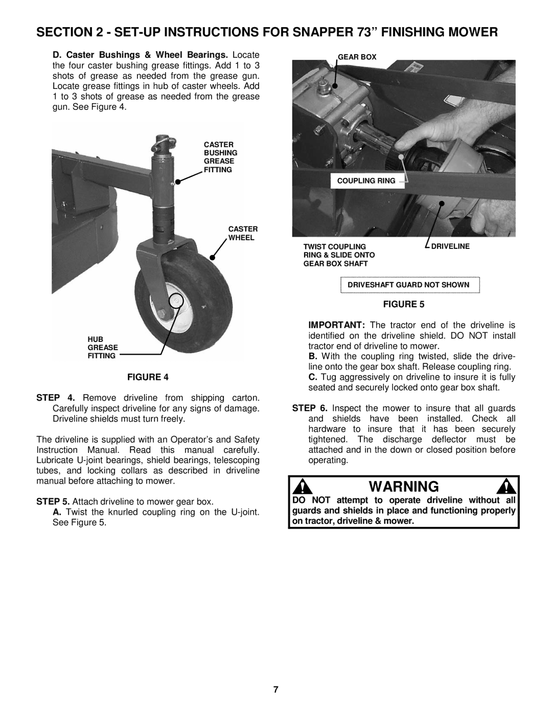
D. Caster Bushings & Wheel Bearings. Locate the four caster bushing grease fittings. Add 1 to 3 shots of grease as needed from the grease gun. Locate grease fittings in hub of caster wheels. Add 1 to 3 shots of grease as needed from the grease gun. See Figure 4.
CASTER
BUSHING
GREASE
FITTING
CASTER
WHEEL
HUB
GREASE
FITTING
FIGURE 4
STEP 4. Remove driveline from shipping carton. Carefully inspect driveline for any signs of damage. Driveline shields must turn freely.
The driveline is supplied with an Operator’s and Safety Instruction Manual. Read this manual carefully. Lubricate
STEP 5. Attach driveline to mower gear box.
A. Twist the knurled coupling ring on the
GEAR BOX
COUPLING RING
TWIST COUPLING | DRIVELINE |
RING & SLIDE ONTO |
|
GEAR BOX SHAFT |
|
DRIVESHAFT GUARD NOT SHOWN
FIGURE 5
IMPORTANT: The tractor end of the driveline is identified on the driveline shield. DO NOT install tractor end of driveline to mower.
B. With the coupling ring twisted, slide the drive- line onto the gear box shaft. Release coupling ring. C. Tug aggressively on driveline to insure it is fully seated and securely locked onto gear box shaft.
STEP 6. Inspect the mower to insure that all guards and shields have been installed. Check all hardware to insure that it has been securely tightened. The discharge deflector must be attached and in the down or closed position before operating.
WARNING
DO NOT attempt to operate driveline without all guards and shields in place and functioning properly on tractor, driveline & mower.
7
