Section 4 - ADJUSTMENTS & REPAIR
WARNING
Before attempting any adjustments or repairs, STOP the engine, remove the spark plug wire from the spark plug and secure wire away from plug. Wear heavy leather gloves when handling or working around cutting blades. Blades are extremely sharp and can cause severe injury. Never use a cutting blade that shows signs of excessive wear or damage.
4.4.1.Engine Drive Belt Replacement (Standard and Stretch Type Belts)
(Continued From Previous Page)
13.Standard Belt: Use a stiff wire, such as a coat hanger, with a hook fashioned on one end to pull the hooked end of the idler spring through the large hole in the right wheel bracket. See Figure 4.20.
14.Reinstall the driven disc assembly.
IDLER
RIGHTSPRING WHEEL
BRACKET
PULL SPRING THROUGH
LARGE HOLE & HOOK INTO
SMALL HOLE
FIGURE 4.20
4.4.2.Transmission
| IDLER |
DRIVE | PULLEY |
DIFFERENTIAL | |
PULLEY | BRACKET |
| |
| BELT |
HEX SHAFT |
|
BELT GUIDE | DRIVEN |
| PULLEY |
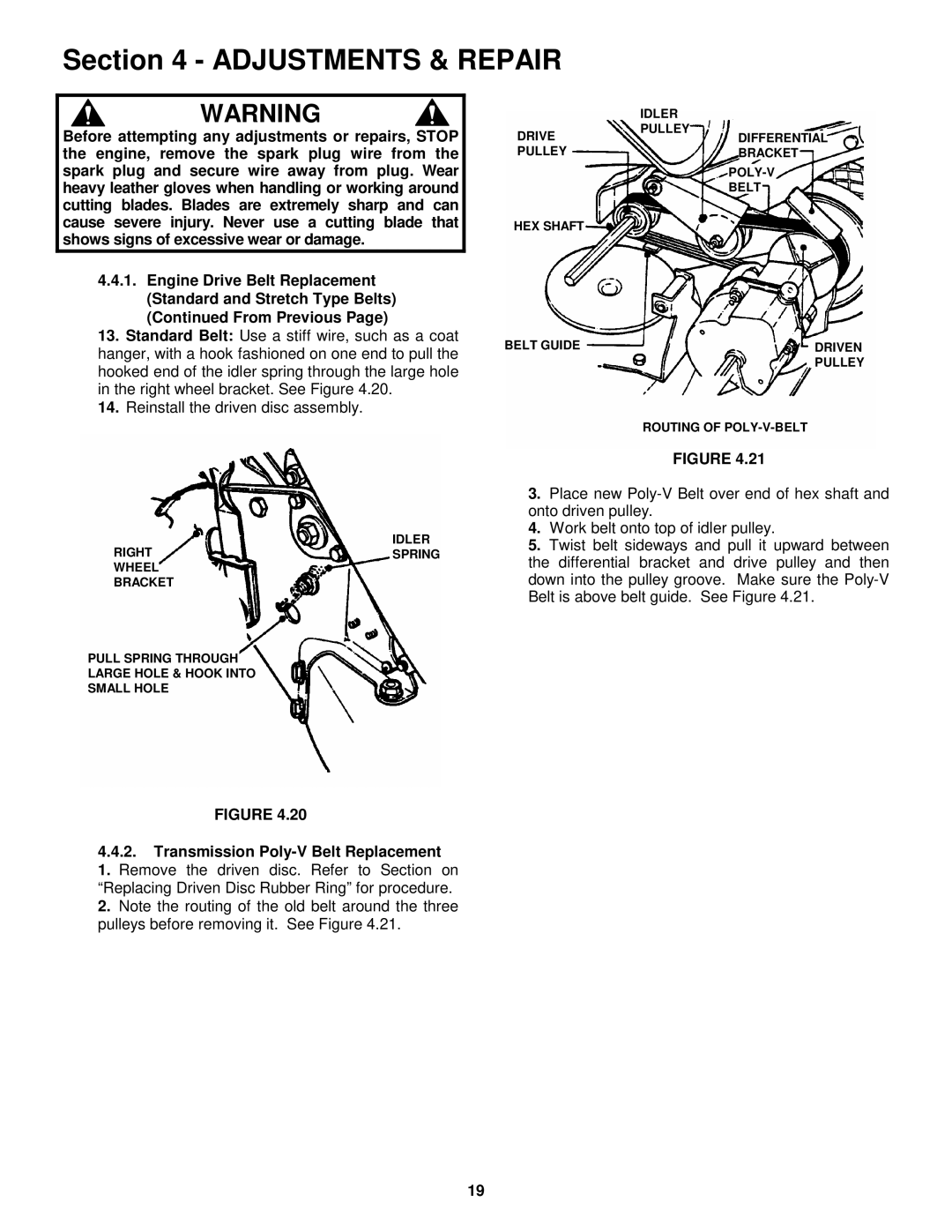
ROUTING OF
FIGURE 4.21
3.Place new
4.Work belt onto top of idler pulley.
5.Twist belt sideways and pull it upward between the differential bracket and drive pulley and then down into the pulley groove. Make sure the
19