5.2.13Motion control linkage adjustment.
![]() WARNING
WARNING
POTENTIAL HAZARD
♦Engine must be running and drive wheels must be turning so motion control adjustment can be performed.
WHAT CAN HAPPEN
♦Contact with moving parts or hot surfaces may cause personal injury.
HOW TO AVOID THE HAZARD
♦Keep fingers, hands, and clothing clear of rotating components and hot surfaces.
![]() CAUTION
CAUTION
POTENTIAL HAZARD
♦Raising the mower deck for service or maintenance relying solely on mechanical or hydraulic jacks could be dangerous.
WHAT CAN HAPPEN
♦The mechanical or hydraulic jacks may not be enough support or may malfunction allowing the unit to fall, which could cause injury.
HOW TO AVOID THE HAZARD
♦DO NOT rely solely on mechanical or hydraulic jacks for support. Use adequate jack stands or equivalent support.
a)This adjustment must be made with the drive wheels turning. First raise the frame and block up so that drive wheels can rotate freely.
b)Remove the electrical connection from the seat safety switch, located directly to the left of the seat switch assembly beside the hydraulic oil reservoir.
Temporarily install a jumper wire across the terminals in the connector of the wiring harness.
c)Run the unit at least 5 minutes with the drive levers at full forward speed to bring hydraulic system oil up to operating temperature.
d)Unhook seat latch and tilt seat forward.
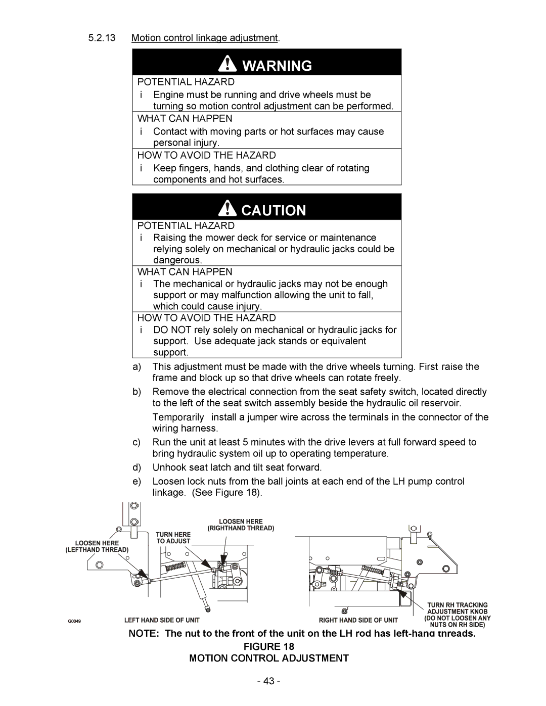
e)Loosen lock nuts from the ball joints at each end of the LH pump control linkage. (See Figure 18).
NOTE: The nut to the front of the unit on the LH rod has
FIGURE 18
MOTION CONTROL ADJUSTMENT
- 43 -