Manuals
/
Exmark
/
Lawn and Garden
/
Lawn Mower
Exmark
Lazer HP
manual
Hydraulic Diagram
Models:
Lazer HP
1
54
60
60
Download
60 pages
15.67 Kb
51
52
53
54
55
56
57
58
Troubleshooting
Specification
Install
Lubrication Chart
Safety Alert Symbol
Dimension
Maintenance
Problem
Assembly Instructions
Service Battery
Page 54
Image 54
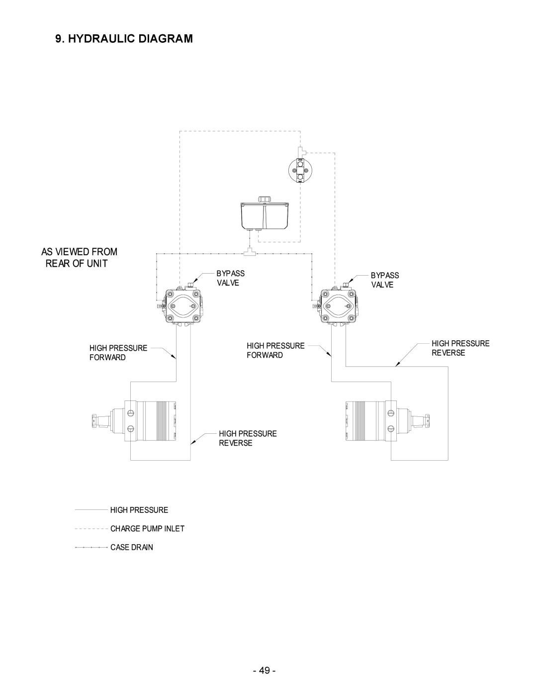
9. HYDRAULIC DIAGRAM
- 49 -
Page 53
Page 55
Page 54
Image 54
Page 53
Page 55
Contents
For Serial Nos 440,000 & Higher
Potential Hazard
Exmark Parts PLUS Program
Operators Manual
Table of Contents
Safety Alert Symbol
Safety
Your Safety is Involved
Training
Carbon monoxide can kill you
Potential Hazard
Operation
Safe Zone for Mowing
There is no rollover protection when the roll bar is down
Maintenance and Storage
For Kawasaki Liquid-Cooled units
Safety Signs
Page
Location RH Side on Top
Specifications
Hydrostatic Ground Drive System
Tires
Cutting Deck
Dimensions
Torque Requirements
Assembly Instructions
Uncrate Mower Install Rollover Protection System Roll BAR
Lower Roll BAR Installation
Service Battery
Upper Roll BAR Installation
Machine is shipped with a filled lead acid battery
Install Drive Wheels
Install Motion Control Levers
Check Tire Pressure
Service Engine Service Engine Coolant
Position Discharge Chute
Controls
Service Hydraulic OIL
Operation Instructions
Motion Control Positions
Potential Hazard
Push the lever forward and down to disengage the brake
PRE-START
Operating Instructions
Transporting
Do not drive a unit on a public street or roadway
Maintenance & Adjustments
Periodic Maintenance
Service Interval Daily
Service Interval Monthly
Service Interval Daily or more often in dry conditions
Blade Bolt Installation
Service Interval Daily
Service Interval 50 hours
Service Interval 100 hrs
Coolant Plug Location
Service Interval 40 hr
Service Interval 40 hrs
Lubrication Chart
Service Interval Refer to chart
Service Interval Once Yearly
Caster Wheel Assembly
Service Interval 160 hrs
Service Interval As Required
Service Interval After First 250 hrs Then yearly thereafter
Adjustments
Service Interval 500 hrs
ANTI-SCALP Roller Adjustment
Cutting Height Position
Swivel Adjustment Spring Compression Adjustment
Self-tensioning No adjustment necessary
Mule Drive Belt Adjustment
Brake Adjustment
Belt Guide Positioning
No adjustment necessary
Reverse Indicator Adjustment
Throttle Tension
Motion Control Adjustment
Caster Adjustment
Armrest Adjustment
Motor OIL Disposal
Mercury Switch Disposal
Waste Disposal
Engine Coolant Disposal
Mower Pulls Left or Right W/LEVERS Fully Forward
Trouble Shooting
Battery Disposal
Mower Cuts Unevenly
Engine Troubleshooting Table
Problem
Engine Warning Systems
Electrical Diagram
Hydraulic Diagram
Limited Warranty Exmark Turf Equipment
Page
Page
Service Record
Page
See EXMARK’S Complete Line of Products for Turf Care
Top
Page
Image
Contents