a)Stop engine, wait for all moving parts to stop, and remove key.
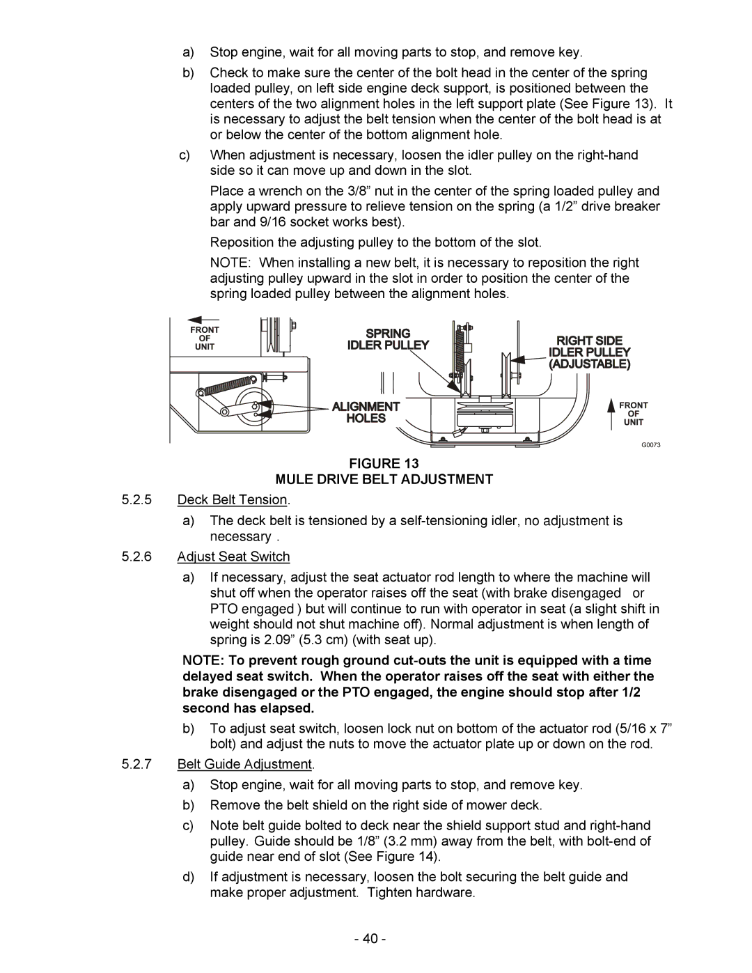
b)Check to make sure the center of the bolt head in the center of the spring loaded pulley, on left side engine deck support, is positioned between the centers of the two alignment holes in the left support plate (See Figure 13). It is necessary to adjust the belt tension when the center of the bolt head is at or below the center of the bottom alignment hole.
c)When adjustment is necessary, loosen the idler pulley on the
Place a wrench on the 3/8” nut in the center of the spring loaded pulley and apply upward pressure to relieve tension on the spring (a 1/2” drive breaker bar and 9/16 socket works best).
Reposition the adjusting pulley to the bottom of the slot.
NOTE: When installing a new belt, it is necessary to reposition the right adjusting pulley upward in the slot in order to position the center of the spring loaded pulley between the alignment holes.
FIGURE 13
MULE DRIVE BELT ADJUSTMENT
5.2.5Deck Belt Tension.
a)The deck belt is tensioned by a
5.2.6Adjust Seat Switch
a)If necessary, adjust the seat actuator rod length to where the machine will shut off when the operator raises off the seat (with brake disengaged or PTO engaged) but will continue to run with operator in seat (a slight shift in weight should not shut machine off). Normal adjustment is when length of spring is 2.09” (5.3 cm) (with seat up).
NOTE: To prevent rough ground
b)To adjust seat switch, loosen lock nut on bottom of the actuator rod (5/16 x 7” bolt) and adjust the nuts to move the actuator plate up or down on the rod.
5.2.7Belt Guide Adjustment.
a)Stop engine, wait for all moving parts to stop, and remove key.
b)Remove the belt shield on the right side of mower deck.
c)Note belt guide bolted to deck near the shield support stud and
d)If adjustment is necessary, loosen the bolt securing the belt guide and make proper adjustment. Tighten hardware.
- 40 -