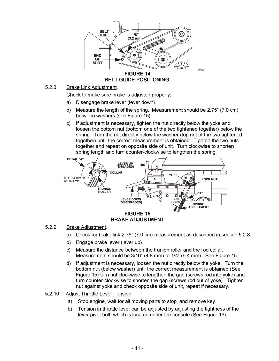
FIGURE 14
BELT GUIDE POSITIONING
5.2.8Brake Link Adjustment.
Check to make sure brake is adjusted properly.
a)Disengage brake lever (lever down).
b)Measure the length of the spring. Measurement should be 2.75” (7.0 cm) between washers (see Figure 15).
c)If adjustment is necessary, tighten the nut directly below the yoke and loosen the bottom nut (bottom one of the two tightened together) below the spring. Turn the nut directly below the washer (top nut of the two tightened together) until the correct measurement is obtained. Tighten the two nuts together and repeat on opposite side of unit. Turn clockwise to shorten spring length and turn
3/16” (4.8 mm) to 1/4” (6.4 mm)
2.75” (7.0 cm) ![]()
FIGURE 15
BRAKE ADJUSTMENT
5.2.9Brake Adjustment.
a)Check for brake link 2.75” (7.0 cm) measurement as described in section 5.2.8.
b)Engage brake lever (lever up).
c)Measure the distance between the trunion roller and the rod collar. Measurement should be 3/16” (4.8 mm) to 1/4” (6.4 mm). See Figure 15.
d)If adjustment is necessary, loosen the nut directly below the yoke. Turn the bottom nut (below washer) until the correct measurement is obtained (See Figure 15) turn nut clockwise to lengthen the gap (screws rod into yoke) and turn
5.2.10Adjust Throttle Lever Tension.
a)Stop engine, wait for all moving parts to stop, and remove key.
b)Tension in throttle lever can be adjusted by adjusting the tightness of the lever pivot bolt, which is located under the console (See Figure 16).
-41 -