SET-UP INSTRUCTIONS & PRE-OPERATIONAL CHECKLIST for SNAPPER
INTERMEDIATE REAR TINE TILLER
INTRODUCTION: Uncrate unit and check for any damage and report immediately. Make repairs as necessary. The
handle is shipped reversed and attached to the handle bracket to allow overall lower profile for shipment. The two #2- 8725 Hex Cap Screw and two #9-1606 Lock Nut in #6-1794 Hardware Bag are spare pieces for securing tines in case of shear bolt failure during operation. Keep these pieces for future use.
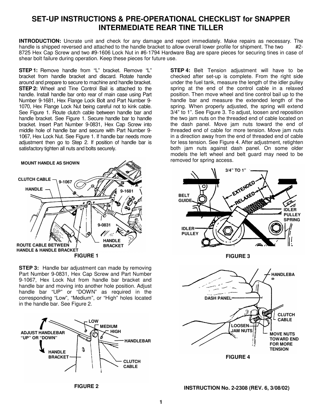
STEP 1: Remove handle from “L” bracket. Remove “L” bracket from handle bracket and discard. Rotate handle around and prepare to secure to machine and handle bracket. STEP 2: Wheel and Tine Control Bail is attached to the handle. Install handle bar onto rear of main case using Part Number 9-1681, Hex Flange Lock Bolt and Part Number 9- 1070, Hex Flange Lock Nut being careful not to kink cable. See Figure 1. Route clutch cable between handle bar and handle bracket. See Figure 1. Secure handle bar to handle bracket. Insert Part Number 9-0831, Hex Cap Screw into middle hole of handle bar and secure with Part Number 9- 1067, Hex Lock Nut. See Figure 1. If handle bar needs more adjustment then go to Step 2. If position of handle bar is satisfactory tighten all nuts and bolts securely.
MOUNT HANDLE AS SHOWN
CLUTCH CABLE | 9-1067 |
|
HANDLE | 9-1681 |
|
9-0831
HANDLE
ROUTE CABLE BETWEENBRACKET
HANDLE & HANDLE BRACKET
FIGURE 1
STEP 3: Handle bar adjustment can made by removing Part Number 9-0831, Hex Cap Screw and Part Number
9-1067, Hex Lock Nut from handle bar bracket and handle bar and moving into another hole position. Adjust handle bar “UP” or “DOWN” as required in the corresponding “Low”, “Medium”, or “High” holes located in the handle bar. See Figure 2.
LOW
MEDIUM
ADJUST HANDLEBARHIGH
“UP” OR “DOWN”
HANDLEBAR
HANDLE
BRACKET
CLUTCH
CABLE
STEP 4: Belt Tension adjustment will have to be checked after set-up is complete. From the right side under the fuel tank, measure the length of the idler pulley spring at the end of the control cable in a relaxed position. Then move wheel and tine control bail up to the handle bar and measure the extended length of the spring. When properly adjusted, the spring will extend 3/4” to 1”. See Figure 3. To adjust, loosen and reposition the two jam nuts on the threaded end of cable located on the dash panel. Move jam nuts toward the end of threaded end of cable for more tension. Move jam nuts in a direction away from the end of threaded end of cable for less tension. See Figure 4. After adjustment, retighten both jam nuts against dash panel. On some older models the left wheel and belt guard may need to be removed for spring access.
3/4” TO 1”
BELT
GUIDE
IDLER
PULLEY
SPRING
IDLER
PULLEY
FIGURE 3
HANDLEBA
R
DASH PANEL
CLUTCH
CABLE
LOOSEN
JAM NUTS
MOVE NUTS
TOWARD END
FOR MORE
TENSION
FIGURE 4
FIGURE 2 | INSTRUCTION No. 2-2308 (REV. 6, 3/08/02) |
|