Section 2 - OPERATING INSTRUCTIONS
2.2STARTING & OPERATION
2.2.2.PROPELLING MOWER (Self Propelled Models Only)
1.Start engine. Refer to Section “Starting & Operation – Engine & Blade”.
2.Move ground speed control to the desired speed position. See Figure 2.6.
3.Squeeze wheel drive control against handle to engage wheel drive and propel mower forward. Forward speed can be adjusted while mower is moving by changing position of ground speed control. See Figure 2.6.
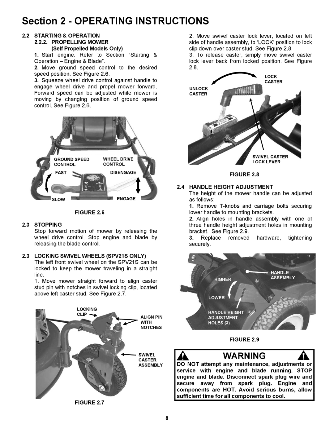
2.Move swivel caster lock lever, located on left side of handle assembly, to ‘LOCK’ position to lock clip down over caster stud. See Figure 2.8.
3.To release caster, simply move swivel caster lock lever back from locked position. See Figure
LOCK CASTER
UNLOCK
CASTER
| GROUND SPEED | WHEEL DRIVE |
| |||
| CONTROL | CONTROL |
| |||
|
|
|
|
| DISENGAGE |
|
|
|
|
|
|
| |
| FAST |
|
|
|
| |
|
|
|
|
|
|
|
SLOWENGAGE
FIGURE 2.6
2.3STOPPING
Stop forward motion of mower by releasing the wheel drive control. Stop engine and blade by releasing the blade control.
2.3LOCKING SWIVEL WHEELS (SPV21S ONLY) The left front swivel wheel on the SPV21S can be locked to keep the mower traveling in a straight line:
1. Move mower straight forward to align caster stud pin with notches in swivel locking clip, located above left caster stud. See Figure 2.7.
LOCKING
CLIP ![]() ALIGN PIN
ALIGN PIN
WITH
NOTCHES
SWIVEL
CASTER
ASSEMBLY
FIGURE 2.7
SWIVEL CASTER
LOCK LEVER
FIGURE 2.8
2.4HANDLE HEIGHT ADJUSTMENT
The height of the mower handle can be adjusted as follows:
1.Remove
2.Align holes in handle assembly with one of three handle height adjustment holes in mounting bracket. See Figure 2.9.
3.Replace removed hardware, tightening securely.
HANDLE
HIGHERASSEMBLY
LOWER
HANDLE HEIGHT
ADJUSTMENT
HOLES (3)
FIGURE 2.9
WARNING
DO NOT attempt any maintenance, adjustments or service with engine and blade running. STOP engine and blade. Disconnect spark plug wire and secure away from spark plug. Engine and components are HOT. Avoid serious burns, allow sufficient time for all components to cool.
8